Table of Contents
Advertisement
Quick Links
OWNER'S MANUAL &
RAK148H2
........................................3
..................................... 16
LIAF271
49-7757-1 01-20 GEA
....................2
................................ 4
..........................8
.................10
............... 12
.................. 13
....................... 15
Advertisement
Table of Contents

Related Manuals for GE RAK148H2


Summary of Contents for GE RAK148H2
-
Page 1: Table Of Contents
OWNER’S MANUAL & INSTRUCTIONS INSTALLATION RAK148H2 ....2 SAFETY INFORMATION ........3 OVERVIEW ........ 4 INSTALLATION ......8 WIRING DIAGRAMS ....10 CONFIGURATION MODE ....12 OPERATING FUNCTIONS ....13 TESTING THERMOSTAT ....... 15 TROUBLESHOOTING ........16 WARRANTY LIAF271 49-7757-1 01-20 GEA... -
Page 2: Safety Information
1-stage cool, 2-speed fan • Alternate Setting: 1-stage heat (resistance heat), 1-stage cool, 2-speed fan Terminations: R, C, W, Y, GH, GL, B (RAK148H2) Wiring: Maximum wiring length is 66ft (20 meters) for AWG18 Maximum wiring length is 60ft (18 meters) for... -
Page 3: Overview
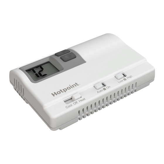
INTRODUCTION OVERVIEW THERMOSTAT CONTROLS Display Up/Down Buttons High High Cool Cool Off Off Heat Heat Auto Auto Function Switch Fan Auto/On Switch Fan Speed Switch THERMOSTAT BASE LAYOUT Display Up/Down Buttons Wiring Channel Mounting Hole Mounting Hole LEFT LEFT RIGHT RIGHT RESET RESET... -
Page 4: Installation Instructions
INSTALLATION INSTRUCTIONS WARNING ELECTRICAL SHOCK HAZARD—Turn off power by unplugging the unit or by removing the fuse or switching the appropriate circuit breaker to the OFF position before removing the existing thermostat. Failure to do so could result in risk of electric shock. PACKAGE CONTENTS/TOOLS REQUIRED Package includes: Thermostat base, thermostat cover,... - Page 5 INSTALLATION INSTRUCTIONS TO REMOVE EXISTING THERMOSTAT 1. Turn off power to heating and cooling system by removing the fuse or switching off the appropriate circuit breaker. 2. Remove cover of old thermostat. This should expose the wires. 3. Label the existing wires with the enclosed wire labels before removing wires.
- Page 6 INSTALLATION INSTRUCTIONS TO INSTALL THERMOSTAT IMPORTANT: Thermostat installation must conform to local and national building and electrical codes and ordinances. NOTE: Mount the thermostat about five feet above the floor. Do not mount the thermostat on an outside wall, in direct sunlight, behind a door or in an area affected by a vent or duct.
- Page 7 INSTALLATION INSTRUCTIONS TO INSTALL THERMOSTAT (cont.) 10. Seal hole for wires behind thermostat with non- flammable insulation or putty, or use a wall plate obtainable from a local hardware or home building store. 11. Use supplied screws to mount thermostat base to wall.
-
Page 8: Wiring Diagrams
WIRING DIAGRAMS Table 1: Terminals for six wires 1-stage heat/1-stage cool system... - Page 9 WIRING DIAGRAMS Table 2: Terminals for seven wires 2-stage heat/1-stage cool system...
-
Page 10: Configuration Mode
CONFIGURATION MODE The configuration mode is used to set the RAK148H2 to match the heating/cooling system. This thermostat function with up to 2-stage heat pump systems. To configure the RAK148H2, perform the following steps: Note: Operation being set will blink in the display. - Page 11 CONFIGURATION MODE Press the button to set differential value. Press the RIGHT button to advance to the next screen. Note: Default factory setting is 2°F/1°C for each stage. 4. Temperature Differential—Stage 2 (1–9°F/1–5°C) Heat Pump (HSH) only Set the number of degrees between when stage 1 turns on and stage 2 turns on.
-
Page 12: Operating Functions
OPERATING FUNCTIONS • In this mode, the thermostat will not turn on the heating or cooling devices (manual fan can operate). • Off is also used to access Configuration mode. Cool • In this mode, the thermostat controls the cooling system. •... -
Page 13: Testing Thermostat
TESTING THE THERMOSTAT Once the thermostat is installed, it should be thoroughly tested. NOTICE Do not use air conditioning beyond the simple test when the outdoor temperature is below 50 degrees. This can damage the air conditioning system. Note: Before testing the thermostat, move the Fan Auto/On switch to the Auto position. - Page 14 TESTING THE THERMOSTAT Heat Test 1. Slide Function switch to Heat position. Heat mode screen is displayed. 2. Adjust set temperature so it is 5 degrees above room temperature. 3. Heat should come on within a few seconds. 4. Adjust the set temperature so it is 2 degrees below the room temperature and the heat should turn off.
-
Page 15: Troubleshooting
TROUBLESHOOTING TIPS Problem Solution No Display Check for 24 VAC; display is blank when 24 VAC is not present System fan does not Verify that wiring is correct. come on properly All thermostat but- Verify that 24 VAC is present; unit tons are inoperative will not operate when 24 VAC is not present. -
Page 16: Warranty
To know what your legal rights are, consult your local, state or provincial consumer affairs office or your state’s Attorney General. Warrantor: GE Appliances, a Haier company Louisville, KY 40225...
Need help?
Do you have a question about the RAK148H2 and is the answer not in the manual?
Questions and answers