Table of Contents
Advertisement
Owner's Manual &
Installation Instructions
RAK149P2
INFORMATION ............................. 2
SPECIFICATIONS ........................ 2
INTRODUCTION OVERVIEW ..... 3
CONFIGURATION MODE ............ 8
OPERATING FUNCTIONS ......... 10
TESTING THE THERMOSTAT ... 11
PROGRAMMING ..........................13
LOW BATTERY ...........................17
TROUBLESHOOTING TIPS .......20
LIMITED WARRANTY ...............24
GE is a trademark of the General Electric Company.
Manufactured under trademark license.
49-5000517 Rev. 2 10-20 GEA
Advertisement
Table of Contents

Related Manuals for GE RAK149P2


Summary of Contents for GE RAK149P2
-
Page 1: Table Of Contents
OPERATING FUNCTIONS ..10 TESTING THE THERMOSTAT ... 11 PROGRAMMING ......13 LOW BATTERY ......17 POWER FAILURE INDICATOR .18 TROUBLESHOOTING TIPS ..20 LIMITED WARRANTY ....24 GE is a trademark of the General Electric Company. Manufactured under trademark license. 49-5000517 Rev. 2 10-20 GEA... -
Page 2: Important Safety Information
IMPORTANT SAFETY INFORMATION READ ALL INSTRUCTIONS BEFORE USING WARNING FIRE AND SHOCK HAZARD • Always turn off power at the main power supply before installing, cleaning or removing the thermostat. Failure to do so could result in electrical shock hazard. •... -
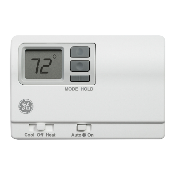
Page 3: Introduction Overview
INTRODUCTION OVERVIEW THERMOSTAT CONTROL Display Up/Down Buttons MODE HOLD Cool Off Heat Auto Function Switch Fan Auto/On Switch Mode/Hold Switch PARTS DIAGRAM Up/Down Buttons Display Mode/Hold Switch Wiring Channel Mounting Hole Mounting Hole RESET B G Y W C R Reset 2 “AAA”... -
Page 4: Installation Instructions
INSTALLATION INSTRUCTIONS WARNING ELECTRICAL SHOCK HAZARD—Turn off power by unplugging the unit or by removing the fuse or switching the appropriate circuit breaker to the OFF position before removing the existing thermostat. Failure to do so could result in risk of electric shock. PACKAGE CONTENTS/ TOOLS REQUIRED Package includes: Thermostat on base, thermostat cover,... - Page 5 INSTALLATION INSTRUCTIONS TO INSTALL THERMOSTAT (cont.) Turn off power to the heating and cooling system by removing the fuse or switching off the appropriate circuit breaker. Move the Function switch on the thermostat to Off. Remove the cover by inserting and twisting a coin or screwdriver in the slots on the top of the thermostat.
- Page 6 INSTALLATION INSTRUCTIONS TO INSTALL THERMOSTAT (cont.) 14. Insert two “AAA” batteries into battery holder. Verify that they are oriented as shown on battery holder. 15. Replace cover on thermostat by snapping it in place. 16. Plug the unit in or turn on power to the system at the main service panel.
- Page 7 INSTALLATION INSTRUCTIONS Table 2: Terminals for six wires 2-stage heat/1- stage cool system Note: Connect G terminal of thermostat to Zoneline GL terminal for low fan speed or terminal GH for high fan speed. Only one can be selected. 49-5000517 Rev. 2...
-
Page 8: Configuration Mode
Press the Hold button to advance to the next screen. NOTE: Default factory setting is Fahrenheit. 2. Heat System—Check model number on the GE PTAC chassis to determine the primary heating method. AZ65H/95H***** are heat pumps and is the thermostat factory setting. - Page 9 Configuration mode 3. Temperature Differential—Stage 1—(1–9°F) (1–5°C) Set the number of degrees between the “setpoint” temperature and the “turn on” temperature for first stage. Press the button to set differential value. Press the HOLD button to advance to the next screen. Note: Default factory setting is 2°F/1°C for each stage.
-
Page 10: Operating Functions
Operating functions • In this mode, the thermostat will not turn on the heating or cooling devices (manual fan can operate). • Off is also used to access Setup and Program modes. Cool • In this mode, the thermostat controls the COOL cooling system. -
Page 11: Testing The Thermostat
Testing the thermostat Once the thermostat is installed, it should be thoroughly tested. CAUTION Do not use air conditioning when the outdoor temperature is below 50 degrees. This can damage the air conditioning system. Note: Before testing the thermostat, move the Fan Auto/On switch to the Auto position. - Page 12 Testing the thermostat Heat Test 1. Slide Function switch to Heat position. Heat mode screen is HEAT displayed. 2. Adjust set temperature so it is 5 degrees above room temperature. 3. Heat should come on within a few seconds. 4. Adjust the set temperature so it is 2 degrees below the room temperature and the heat should turn off.
-
Page 13: Programming
Programming Factory Programming Settings The programmable thermostat comes preprogrammed with the following schedule: MONDAY MORN 6:00 8:00 6:00 NITE 10:00 through HEAT 70 F HEAT 62 F HEAT 70 F HEAT 62 F SUNDAY COOL 78 F COOL 85 F COOL 78 F COOL 82 F Setting the time and day of the week The time and day of the week must be set for the program schedule to operate correctly. - Page 14 Programming Program Overview The programmable thermostat has four periods (MORN, DAY, EVE, NITE) that are customizable for each day of the week. Each period will have a set time, heat temperature and cool temperature. The thermostat monitors the day and time, while maintaining the specific conditions that you have chosen for each period in the program.
- Page 15 9. Press the Hold button to advance to the next screen parameter. • Heat temperature is displayed (60°F HEAT to 85°F) / (15°C to 29°C). Note: Transitions required after 11:59 PROG MORN PM must be programmed in the next days MORN period. 10.
- Page 16 Programming Use the following personal program schedule to record your settings: MONDAY 01 MORN NITE HEAT HEAT HEAT HEAT COOL COOL COOL COOL TUESDAY 02 MORN NITE HEAT HEAT HEAT HEAT COOL COOL COOL COOL WEDNESDAY 03 MORN NITE HEAT HEAT HEAT HEAT...
-
Page 17: Low Battery
Low battery indicator The programmable thermostats with battery backup have a low battery warning screen. Low battery warning The thermostat will display a low battery indication. The low battery warning will be flashing until batteries are replaced. 49-5000517 Rev. 2... -
Page 18: Power Failure Indicator
Power failure Indicator The programmable thermostats with battery backup also will indicate a main power failure when the 24 VAC power from the room air conditioner is not present. Power failure The thermostat will display a power failure indication (“PF”) on the screen. Note: If “PF”... - Page 19 Notes 49-5000517 Rev. 2...
-
Page 20: Troubleshooting Tips
Troubleshooting tips Problem Solution No Display Check for 24 VAC at thermostat and- batteries; display is blank when 24 VAC is not present and batteries are bad. System fan does not Verify that wiring is correct. come on properly All thermostat buttoms Verify that 24 VAC is present;... - Page 21 Troubleshooting tips Problem Solution Fan doesn’t run or turn This is normal. On some models, the changing function or time delay. setting Replace batteries with 2 fresh “AAA” displays on screen alkaline batteries. “PF” displays on Check for 24 VAC at thermostat. screen.
- Page 22 Notes 49-5000517 Rev. 2...
- Page 23 Notes 49-5000517 Rev. 2...
-
Page 24: Limited Warranty
For Warranty replacement, contact your distributor. What GE Appliances Will Not Cover: Service trips to your location. Improper installation. If you have an installation problem, contact connections to the product.
Need help?
Do you have a question about the RAK149P2 and is the answer not in the manual?
Questions and answers