Table of Contents
Advertisement
Available languages
Available languages
Quick Links
INSTRUCTIONS
INSTALLATION
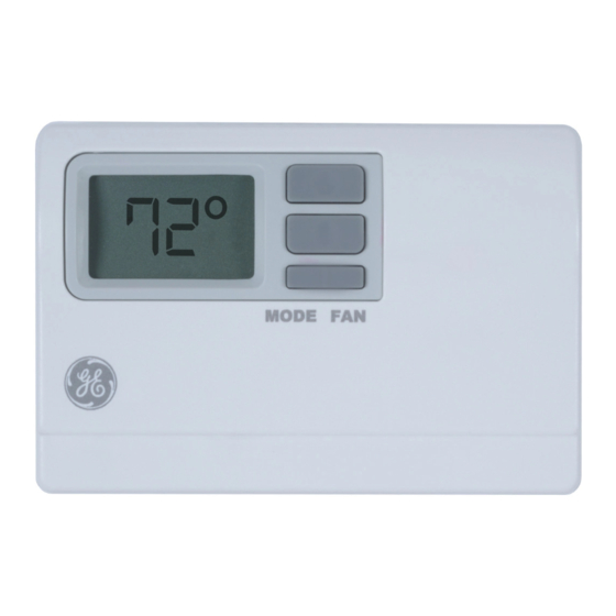
RAK150VF2
....................2
SAFETY INFORMATION
........................................3
OVERVIEW
................................ 4
..........................8
.................10
............... 13
....................... 15
..................................... 16
31-5000604 Rev. 1 02-22 GEA
Advertisement
Chapters
Table of Contents

Related Manuals for GE RAK150VF2


Summary of Contents for GE RAK150VF2
-
Page 1: Table Of Contents
INSTRUCTIONS INSTALLATION RAK150VF2 ....2 SAFETY INFORMATION ........3 OVERVIEW ........ 4 INSTALLATION ......8 WIRING DIAGRAMS ....10 CONFIGURATION MODE ....13 OPERATING FUNCTIONS ....... 15 TROUBLESHOOTING ........16 WARRANTY 31-5000604 Rev. 1 02-22 GEA... - Page 2 IMPORTANT SAFETY INFORMATION READ ALL INSTRUCTIONS BEFORE USING WARNING FIRE AND SHOCK HAZARD • Always turn off power at the main power supply before installing, cleaning or removing the thermostat. Failure to do so could result in electrical shock hazard. •...
- Page 3 INTRODUCTION OVERVIEW THERMOSTAT CONTROLS Display Up/Down Buttons MODE FAN THERMOSTAT BASE LAYOUT Display Up/Down Buttons Wiring Channel Mounting Hole Mounting Mode Hole R C B Y1 W Y2 GL GH RESET CONFIG Reset Configuration Button Button...
- Page 4 INSTALLATION INSTRUCTIONS WARNING ELECTRICAL SHOCK HAZARD — Turn off power by unplugging the unit or by removing the fuse or switching the appropriate circuit breaker to the OFF position before removing the existing thermostat. Failure to do so could result in risk of electric shock.
- Page 5 INSTALLATION INSTRUCTIONS TO REMOVE EXISTING THERMOSTAT 1. Turn off power to heating and cooling system by removing the fuse or switching off the appropriate circuit breaker. 2. Remove cover of old thermostat. This should expose the wires. 3. Label the existing wires with the enclosed wire labels before removing wires.
-
Page 6: Installation
INSTALLATION INSTRUCTIONS TO INSTALL THERMOSTAT IMPORTANT: Thermostat installation must conform to local and national building and electrical codes and ordinances. NOTE: Mount the thermostat about five feet above the floor. Do not mount the thermostat on an outside wall, in direct sunlight, behind a door or in an area affected by a vent or duct. - Page 7 INSTALLATION INSTRUCTIONS TO INSTALL THERMOSTAT (cont.) 9. Seal hole for wires behind thermostat with non- flammable insulation or putty, or use a wall plate obtainable from a local hardware or home building store. 10. Use supplied screws to mount thermostat base to wall.
-
Page 8: Wiring Diagrams
WIRING DIAGRAMS Table 1: Terminals for eight wires. 3-stage heat/2- stage cool system... - Page 9 WIRING DIAGRAMS Table 2: Terminals for seven wires. 2-stage heat/1-stage cool system Table 3: Terminals for six wires. 1-stage heat/1- stage cool system...
-
Page 10: Configuration Mode
CONFIGURATION MODE The configuration mode is used to set the RAK150VF2 to match the heating/cooling system. The default setting of this thermostat is for 2-stage cooling with a 3-stage heat pump system. For an alternate configuration, see #7 in the Configuration Mode Settings below. - Page 11 CONFIGURATION MODE 4. Temperature Differential—Stage 3 (1–9°F) (.5-4.5°C) Set the number of degrees between when stage 2 turns on and stage 3 turns on - Press the button to set differential value. - Press the FAN (right) button to advance to the next screen. - Note: Default factory setting is 1°F/.5ºC.
- Page 12 CONFIGURATION MODE 7. Maximum Heat Setpoint (65, 70, 72, 74, 76, 78, 80, 85°F) (18, 21, 22, 23, 24, 26, 27, 29°C) Adjust to control the maximum Heat set temperature allowed. - Press the button to select. - Press the FAN (right) button to advance to the next screen. Note: Default factory setting is 85°F/29°C.
-
Page 13: Operating Functions
OPERATING FUNCTIONS • In this mode, the thermostat will not turn on the heating or cooling devices (manual fan can operate if Continuous Fan mode is enabled). • Off is also used to access Configuration mode. Heat Heating Setpoint Room Temp •... - Page 14 OPERATING FUNCTIONS • Fan operation is available in either low or high speed. • Press the button to select a fan option. Selection will be locked in after 8 seconds. • “Auto” options operate the fan only during a cooling or heating cycle.
-
Page 15: Troubleshooting
TROUBLESHOOTING TIPS Problem Solution No Display Check for 24 VAC; display is blank when 24 VAC is not present System fan does not Verify that wiring is correct. come on properly All thermostat Verify that 24 VAC is present; unit buttons are will not operate when 24 VAC is not inoperative... -
Page 16: Warranty
For Warranty replacement, contact your distributor. What GE Appliances Will Not Cover: Service trips to your location. Improper installation. If you have an installation problem, contact your installer. You are responsible for providing adequate electrical connections to the product. - Page 17 Instructions D’installation RAK150VF2 RENSEIGNEMENTS IMPORTANTS .....2 CONCERNANT LA SÉCURIT ......3 VUE D’ENSEMBLE ........ 4 INSTALLATION ....8 SCHÉMAS DE CÂBLAGE ....10 CONFIGURATION MODE ..13 FONCTIONS D’UTILISATION ... 15 CONSEILS DE DÉPANNAGE ......16 GARANTIE LIMITÉE 31-5000604 Rev. 1 02-22 GEA...
-
Page 18: Renseignements Importants
RENSEIGNEMENTS IMPORTANTS CONCERNANT LA SÉCURITÉ LISEZ TOUTES LES INSTRUCTIONS AVANT D’UTILISER CET APPAREIL RISQUE D’INCENDIE ET AVERTISSEMENT D’ÉLECTROCUTION Mettez toujours l’alimentation électrique hors tension depuis la source d’alimentation électrique principale avant d’installer, de nettoyer ou de retirer le thermostat. N’utilisez pas des tensions supérieures à 30 VAC. Des tensions plus élevées endommageront le thermostat en plus de représenter un risque d’électrocution ou d’incendie. - Page 19 PRÉSENTATION APERÇU COMMANDE DU THERMOSTAT Écran Boutons fléchés MODE FAN DISPOSITION DE LA BASE DU THERMOSTAT Écran Chemin Boutons fléchés câblage Ventilateur Trou de Mode montage Trou de montage R C B Y1 W Y2 GL GH RESET CONFIG Bouton de Bouton de réinitialisation configuration...
- Page 20 INSTRUCTIONS D’INSTALLATION WARNING RISQUE D’ÉLECTROCUTION — Coupez l’alimentation en débranchant l’appareil ou en retirant le fusible ou mettant le disjoncteur approprié à la position OFF (hors tension) avant de retirer le thermostat. L’omission de procéder ainsi peut occasionner un choc électrique. Contenu de l’emballage Couvercle du thermostat Base du thermostat...
- Page 21 INSTRUCTIONS D’INSTALLATION POUR RETIRER LE THERMOSTAT EXISTANT 1. Mettez le système de chauffage et de climatisation hors tension en retirant le fusible ou en déclenchant le disjoncteur approprié. 2. Retirez le couvercle du thermostat à changer. Ceci devrait exposer les fils. 3.
- Page 22 INSTRUCTIONS D’INSTALLATION INSTALLATION DU THERMOSTAT IMPORTANT: L’installation de ce thermostat doit être conforme à tous les codes et tous les règlements des Codes du bâtiment et de l’électricité locaux et nationaux. REMARQUE: Montez le thermostat à une hauteur d’environ 1,5 m (5 pi) au-dessus du plancher. Ne montez pas le thermostat sur un mur extérieur, directement exposé...
-
Page 23: Installation
INSTRUCTIONS D’INSTALLATION INSTALLATION DU THERMOSTAT (cont.) 9. Scellez le trou des fils derrière le thermostat à l’aide d’un isolant ou d’un mastic non inflammables, ou utilisez une plaque murale obtenue auprès d’une quincaillerie. 10. Utilisez les vis fournies pour monter la base du thermostat sur le mur. -
Page 24: Schémas De Câblage
SCHÉMAS DE CÂBLAGE Tableau 1: Bornes pour huit fils. Système de chauffage à 3 étapes/refroidissement à 2 étapes... - Page 25 SCHÉMAS DE CÂBLAGE Tableau 2: Bornes pour sept fils. Système de chauffage à 2 étapes/refroidissement à 1 étape Tableau 3: Bornes pour six fils. Système de chauffage à 1 étape/refroidissement à 1 étape...
- Page 26 MODE DE CONFIGURATION Le mode de configuration est utilisé pour régler le RAK150VF2 afin qu’il corresponde au système de chauffage-refroidissement. La configuration par défaut de ce thermostat correspond à un système à thermopompe à 2 étapes de refroidissement et 3 étapes de chauffage.
- Page 27 MODE DE CONFIGURATION 4. Écart de température — Étape 3 (1–9°F) (.5-4.5°C) Réglez le nombre de degrés entre le moment où l’étape 2 s’active et celui où l’étape 3 s’active - Pressez le bouton pour régler la valeur différentielle. - Pressez le bouton FAN pour avancer à la fenêtre suivante.
- Page 28 MODE DE CONFIGURATION 7. Réglage de chauffage maximal (65, 70, 72, 74, 76, 78, 80, 85°F) (18, 21, 22, 23, 24, 26, 27, 29°C) - Ajustez pour contrôler la température de chauffage maximale permise. - Pressez le bouton pour régler la valeur de l’écart de température.
-
Page 29: Fonctions D'utilisation
FONCTIONS D’UTILISATION OFF (arrêt) • Dans ce mode, le thermostat n’allumera pas les dispositifs de chauffage ou de refroidissement (le ventilateur manuel peut fonctionner). • Le mode OFF sert aussi à accéder aux mode Configuration. Heat (chauffage) Réglage – Temp. •... - Page 30 FONCTIONS D’UTILISATION Le ventilateur • Le ventilateur peut fonctionner en basse ou haute vitesse. • Appuyez sur le bouton pour sélectionner une option de ventilateur. La sélection sera verrouillée après 8 secondes. • Les options « Auto » activent le ventilateur seulement dans le cycle de refroidissement ou de chauffage.
- Page 31 ESSAI DU THERMOSTAT Problème Solution Assurez-vous que la tension est de pas sans cette tension. Le système de ventilation ne se met pas en marche correctement Aucun bouton du Assurez-vous que la tension est de thermostat ne fonctionne. 24 VAC; l’appareil ne fonctionnera pas sans cette tension.
-
Page 32: Garantie Limitée
Pour le remplacement sous garantie, contactez votre distributeur. Ce que GE Appliances ne couvre pas : Frais de déplacement pour réparation vers votre emplacement. Une installation mal effectuée. Si vous avez un problème d’installation, communiquez avec votre installateur.
Need help?
Do you have a question about the RAK150VF2 and is the answer not in the manual?
Questions and answers