Table of Contents
Advertisement
Available languages
Available languages
Quick Links
OWNER'S MANUAL AND
INSTALLATION INSTRUCTIONS
RAK149F2A
...........................................3
.....................................7
.................................... 9
49-5000769 Rev. 1 11-23
..............................2
........................ 4
......................... 6
.........................8
............................10
Advertisement
Chapters
Table of Contents

Related Manuals for GE RAK149F2A


Summary of Contents for GE RAK149F2A
-
Page 1: Table Of Contents
OWNER’S MANUAL AND INSTALLATION INSTRUCTIONS RAK149F2A SPECIFICATIONS ......2 INSTALLATION INSTRUCTIONS ...........3 WIRING ......4 INSTALLER MENU ......6 TEST EQUIPMENT USING THE THERMOSTAT ........7 OVERVIEW TROUBLESHOOTING ......8 ........9 RESETTING FCC STATEMENT ......10 49-5000769 Rev. 1 11-23... -
Page 2: Specifications
SPECIFICATIONS Electrical Rating: Input-Hardwire 20 to 30 VAC, NEC Class II, 50/60 Hz Terminal Load 1.5 A per terminal, 2.5A maximum all terminals combined Setpoint Range 60° to 85° F (16° to 29° C) Rated Differentials Fast Slow (@ 6°F/ Hr): Heat Pump (Heating) 0.9ºF 1.2ºF... -
Page 3: Installation Instructions
INSTALLATION INSTRUCTIONS WIRING Refer to equipment manufacturer’s instructions for specific system wiring information. After wiring, see INSTALLER MENU for proper thermostat configuration. Wiring table shown are for typical systems and describe the thermostat terminal functions. Terminal Designations Terminal Function Low Speed Fan Relay Power (24V) Changeover Terminal-Energized in Cool (O) or Heat (B) for Heat Pump... -
Page 4: Installer Menu
INSTALLATION INSTRUCTIONS Jumper Wire WIRING (cont) Instructions: To convert the system from PTHP to PTAC, change menu item #20 from default HP to AC. Additionally, if you are using this thermostat on a Hotpoint PTAC (non-heat pump), you will need to cut the jumper wire located on the back of the thermostat. - Page 5 INSTALLATION INSTRUCTIONS INSTALLER MENU (cont) Installer’s Description Default Settings Menu # Setting (Hold Menu (flashing icons) 3 Seconds) Algorithm – AC or HP (If HP HP – Heat Pump or is selected, item #32 will be AC – Air Cond. displayed) Heat Cycle Rate (how often the SLO –...
-
Page 6: Test Equipment
INSTALLATION INSTRUCTIONS TEST EQUIPMENT Turn on power to the system. Fan Operation 1.) Move fan switch to Low position. The blower should begin to operate at low speed . 2.) Move fan switch to Auto Low position. The blower should stop immediately. -
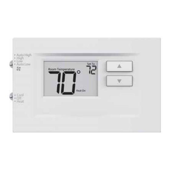
Page 7: Using The Thermostat
USING THE THERMOSTAT THERMOSTAT OVERVIEW Before you begin using your thermostat, you should be familiar with its features, display and the location/operation of the thermostat buttons and switches. THERMOSTAT BUTTONS AND THE DISPLAY SWITCHES 1.) Fan Switch 5.) Thermostat is protecting the equipment from short cycling (5-minute delay) 2.) System Switch 6.) Indicates that the system is running in cool, heat... -
Page 8: Troubleshooting
TROUBLESHOOTING Symptom Possible Cause Corrective Action No Heat/ 1.) Blown fuse or tripped 1.) Replace fuse or reset breaker No Cool/ circuit breaker 2.) Restore power to HVAC unit No Fan 2.) HVAC unit unpowered 3.) Enable wall thermostat control on (common 3.) HVAC unit not set for HVAC unit... -
Page 9: Resetting
TROUBLESHOOTING Symptom Possible Cause Corrective Action Thermostat Thermostat display Display can be adjusted +/-5°. See Display & requires adjustment User Menu item 04 Thermometer Disagree Furnace (Air 1.) The location of Digital thermostats provide precise Conditioner) the thermostat and/ control and cycle faster than older Cycles Too or the size of the mechanical models. -
Page 10: Fcc Statement
FCC STATEMENT NOTE: This equipment has been tested and found to comply with the limits for a Class B digital device, pursuant to part 15 of the FCC Rules. These limits are designed to provide reasonable protection against harmful interference in a residential installation. This equipment generates, uses and can radiate radio frequency energy and, if not installed and used in accordance with the instructions, may cause harmful interference to radio communications. - Page 11 MANUEL D’UTILISATION ET INSTRUCTIONS D’INSTALLATION RAK149F2A SPÉCIFICATIONS ......2 INSTALLATION DU THERMOSTAT ........3 CÂBLAGE ..4 MENU DE L’INSTALLATEUR MISE À L’ESSAI DE ......6 L’ÉQUIPEMENT UTILISATION DU THERMOSTAT ...7 APERÇU DU THERMOSTAT DÉPANNAGE ........8 ......9 RÉINITIALISATION DÉCLARATION DE LA FCC : ...10...
-
Page 12: Spécifications
SPÉCIFICATIONS Paramètres électriques : Câblé 20 à 30 V c.a., NEC classe II, 50/60 Hz Charge à la borne 1,5 A par borne, 2,5 A maximum pour toutes les bornes combinées Plage de réglage 60°F à 85°F (16°C à 29°C) Différentiels nominaux (@ 6 °F/h) Rapide Moyen... -
Page 13: Installation Du Thermostat
INSTALLATION DU THERMOSTAT CÂBLAGE Consultez le mode d’emploi du fabricant de l’appareil pour les informations spécifiques au câblage du système. Après le câblage, consultez la section MENU DE L’INSTALLATEUR pour configurer correctement le thermostat. Les schémas de câblage illustrés correspondent aux systèmes typiques, et ils décrivent les fonctions des bornes du thermostat. -
Page 14: Menu De L'installateur
INSTALLATION DU THERMOSTAT Fil de cavalier CÂBLAGE (cont) Instructions: Pour convertir le système de PTHP à PTAC, modifiez l’élément de menu no 20 de HP (défaut) à AC. De plus, si vous utilisez ce thermostat sur un climatiseur terminal monobloc (PTAC) Hotpoint, vous devrez couper le fil de cavalier situé... - Page 15 (à quelle fréquence la MEd – moyen climatisation s’activera) FAS – rapide Verrouillage du compresseur On – délai de 5 minutes (protège le compresseur contre OFF – aucun délai les cycles trop courts) Temp. de chauffage maximale 85°F 45°F à 99°F...
-
Page 16: Mise À L'essai De L'équipement
INSTALLATION DU THERMOSTAT MISE À L’ESSAI DE L’ÉQUIPEMENT Ouvrez l’alimentation électrique du système. Fonctionnement du ventilateur 1.) Placez le sélecteur du ventilateur à la position basse. Le ventilateur devrait commencer à fonctionner à basse vitesse. 2.) Placez le sélecteur du ventilateur à la position basse automatique. La ventilation devrait s’arrêter immédiatement. -
Page 17: Utilisation Du Thermostat
BOUTONS ET SÉLECTEURS AFFICHAGE DU THERMOSTAT 1.) Sélecteur du ventilateur 5.) Le thermostat protège l’équipement contre les cycles trop courts (délai de 5 minutes) 2.) Sélecteur du système 6.) Indique que le système fonctionne en mode climatisation, chauffage ou auxiliaire (le mode auxiliaire fonctionnera en mode chauffage si la thermopompe ne peut pas maintenir la température... -
Page 18: Dépannage
DÉPANNAGE Problème Cause possible Mesure corrective Chauffage, 1.) Fusible grillé ou disjoncteur 1.) Remplacez le fusible ou réenclenchez climatisation déclenché. le disjoncteur. 2.) Appareil non alimenté. 2.) Rétablissez l’alimentation à l’appareil. ventilateur 3.) Appareil non réglé pour 3.) Activez la commande du thermostat commande de thermostat à... -
Page 19: Réinitialisation
DÉPANNAGE Problème Cause possible Mesure corrective Le point de Le thermomètre du Le thermomètre peut être réglé de +/- 5°. consigne et le thermostat doit être ajusté. Voir le menu de l’utilisateur, article 04. thermomètre ne concordent pas La cadence de 1.) L’emplacement du Les thermostats numériques offrent un l’appareil de... -
Page 20: Déclaration De La Fcc
DÉCLARATION DE LA FCC REMARQUE : Cet équipement a été testé et déclaré conforme aux limites d’un dispositif numérique de Classe B, conformément à la partie 15 des règles de la FCC. Ces limites sont définies afin d’assurer une protection raisonnable contre le brouillage nuisible dans une installation résidentielle.
Need help?
Do you have a question about the RAK149F2A and is the answer not in the manual?
Questions and answers