
Related Manuals for Stealth Products HMO500


Summary of Contents for Stealth Products HMO500
- Page 1 Head Support Hardware HMO500 Owner’s Manual - Maintenance Guide HMO500 Headrest Hardware...
-
Page 2: Table Of Contents
Table of Contents Customer Satisfaction ..............i General ......................i Important Information............... ii-iii Warranty .......................ii Supplier Reference..................ii Warning Labels..................iii Limited Liability..................iii Testing ......................iii Design and Function ..............1-4 Intended Use....................1 Features......................1 Installation Plan ..................1 Installation Overview ................2 Mounting Hardware Parts.............. -
Page 3: Customer Satisfaction
Customer Satisfaction Stealth Products is committed to 100% customer satisfaction. Your complete satisfaction is important to us. Please contact us with feedback or suggestions to help us improve the quality and usability of our products. You may reach us at:... -
Page 4: Important Information
Warranty Our products are designed, manufactured, and produced to the highest of standards. If any defect in material or workmanship is found, Stealth Products will repair or replace the product at our discretion. Any implied warranty, including the implied warranties of merchantability and fitness for a particular purpose, shall not extend beyond the duration of this warranty. -
Page 5: Warning Labels
Stealth Products does not hold responsibility for final integration of final assembly of product to end user. Stealth Products is not liable for user death or injury. Testing Initial setup and driving should be done in an open area free of obstacles until the... -
Page 6: Design And Function
Design and Function Intended Use The HMO500 is a lightweight, multi-axis mounting bracket for use with Stealth's headrests. This hardware is designed to provide multi-axis positioning of the head support, increasing the ability to properly accommodate asymmetrical head positioning. Features The HMO500 hardware: •... -
Page 7: Installation Overview
Design and Function Use the proper tools to install and adjust the HMO500 hardware. The use of improper tools CAUTION may cause damage to the device. Installation • Install the hardware onto the corresponding headrest for the client. • Determine the correct placement of the hardware on the chair. If the height needs to be changed, follow the instructions in the user manual. -
Page 8: Mounting Hardware Parts
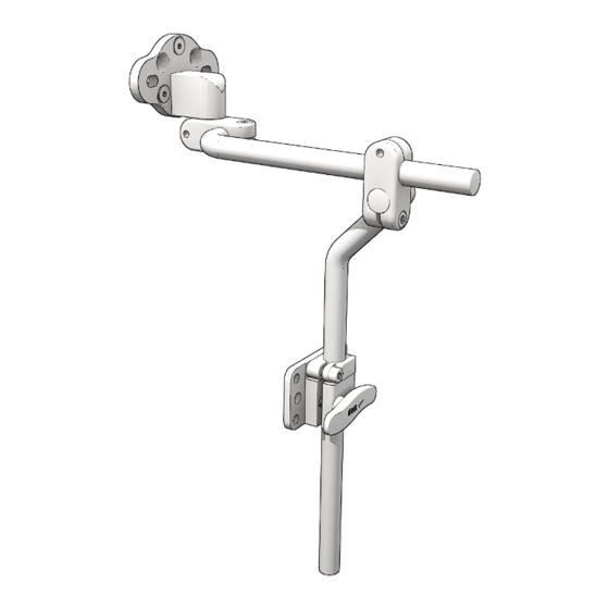
Design & Function Mounting Hardware Parts Description Seat Back Mount Stop Collar Handle Vertical Bar Horizontal Bar Headrest Universal Adapter Plate Bar Clamp M5 x 0.8 x 12mm SHS (5) Headrest Adapter Mount... -
Page 9: Mounting Hardware Packages And Tools
Design & Function Mounting Hardware Packages and Tools tooltip Description Tools 1/4-20 x 5/8 SHS (2) 3mm Allen Wrench/T-Handle* Hardware Package 10-32 x 5/8 SHS (4) 4mm Allen Wrench/T-Handle* Hardware Package M5 x 0.8 x 12mm FHS (4) 3/16" Allen Wrench/T-Handle* 5/32"... -
Page 10: Installation Instructions
Installation Instructions Seat Back Mount Installation Step 1: Determine the necessary screws in order to properly install the Seat Back Mount (A) to the chair. Position the Seat Back Mount (A) on the backrest at the desired height. Secure with corresponding screws provided in the Hardware Pack (1) Step 2: Position the Stop Collar (B) on the vertical bar at the approximate height for installation. - Page 11 Installation Instructions tooltip STEP ¹/₂" more tooltip 6" less tooltip STEP Step 3: Ensure handle (C) has been turned counterclockwise before sliding onto the vertical bar. Insert the vertical bar (D) into the seat back mount. Ensure the stop collar is flush with the seat back mount. Step 4: Turn the handle clockwise to tighten the seat back mount and secure the height adjustment of the vertical bar.
-
Page 12: Depth Adjustment
Installation Instructions Depth Adjustment Step 1: Loosen the M5 (G1) screw on the bar clamp with the 4mm T-Handle/Allen Wrench. Step 2: Slide the horizontal bar (E) to the desired depth. Step 3: When the bar has been adjusted to the desired depth, tighten the M5 screw to secure the depth adjustment. -
Page 13: Angle Adjustment
Installation Instructions Angle Adjustment Two points of angle adjustment are available with the HMO500 hardware: the angle of the horizontal bar can be adjusted, as well as the angle of the headrest adapter plate. Step 1: Loosen the M5 (G1) screw from the bar clamp with the 4mm T-Handle/ Allen Wrench. - Page 14 Installation Instructions After the horizontal bar has been properly adjusted and is in the desired position, the angle adjustment of the adapter plate must be adjusted in order to mount flush with the headrest. Follow the steps below to adjust the adapter plate in the correct position.
- Page 15 Installation Instructions tooltip tooltip ³/₄" ¹/₈" 45° The height of the Universal Adapter Plate NOTICE can move a maximum of 3 1/8" vertically when the angle of the horizontal bar is raised to 45°. The horizontal bar should be adjusted NOTICE no more than a maximum of 45°.
-
Page 16: Adapter Plate Adjustment
Installation Instructions Adapter Plate Adjustment To adjust the position of the adapter plate and the direction in which it will mount to the headrest, follow the directions below: Step 1: Loosen the M5 screw (G1) on the bar clamp with 4mm T-Handle/Allen Wrench. -
Page 17: Headrest Installation, Option 1
Installation Instructions Headrest Installation, Option 1 To install the HMO500 hardware onto a 3-hole pattern headrest, follow the steps below: tooltip Step 1: Determine the hole pattern required for proper headrest installation. Align the headrest to the universal adapter plate. -
Page 18: First-Time Use
If needed, adjust the hardware to proper position. Explain to the client the possible problems and how to address them. Conditions of Use The HMO500 headrest hardware is intended for use as installed by the dealer, in accordance to the installation and instructions in this manual. •... -
Page 19: Care And Maintenance
Care and Maintenance We recommend that the hardware be checked for wear and function on a periodic basis and replaced, if necessary, by a wheelchair professional. • Discontinue use after identifying loose or broken components. • Check and tighten all screws according to the installation instructions. •... - Page 20 © 2022, Stealth Products, LLC Warranty Information Home Page Online User Manual Stealth Products, LLC · info@stealthproducts.com · www.stealthproducts.com (800) 965-9229 | (512) 715-9995 | 104 John Kelly Drive, Burnet, TX 78611 P17D428R2 HMO500.afpub Dec 4, 2023...
Need help?
Do you have a question about the HMO500 and is the answer not in the manual?
Questions and answers