urmet domus 2VOICE 1083 Installation Handbook
Intercom interface for pbx
Hide thumbs
Also See for 2VOICE 1083:
- Installation and use manual (56 pages) ,
- Installation quick manual (56 pages) ,
- Manual (52 pages)

Related Manuals for urmet domus 2VOICE 1083


Summary of Contents for urmet domus 2VOICE 1083
- Page 1 Mod. 1083 DS1083-168 LBT21219 2VOICE INTERCOM INTERFACE FOR PBX Ref. 1083/87 Interactive Links OOOOOOOOO INSTALLATION HANDBOOK...
-
Page 2: Table Of Contents
Interactive Links The document contains INTERACTIVE LINKS for faster and more efficient consultation. INDEX GENERAL DESCRIPTION ........................2 DESCRIPTION OF COMPONENTS ......................3 WARNINGS FOR INSTALLERS ....................... 3 INSTALLATION ............................4 4.1 TERMINAL DESCRIPTION ......................5 4.2 DIP-SWITCH SEQ APT ........................ -
Page 3: Description Of Components
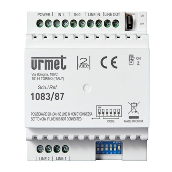
DESCRIPTION OF COMPONENTS Terminals for connection to the PSTN telephone line or a PBX extension Jumper for adjusting line termination Z (default: ON) Terminals for connection to the 2Voice system BUS Configuration dip switch (CODE) - no. 2÷8: define the user code using the interface in the column - no. -
Page 4: Installation
• Make sure that the plate data corresponds to the power specifications before connecting the devices to the mains. • Provide a suitable cut-off and protection master switch upstream from the devices, with contacts open by at least 3 mm. •... -
Page 5: Terminal Description
4.1. TERMINAL DESCRIPTION Terminal board (1) Input for PSTN telephone line or PBX extension line Input for PSTN telephone line or PBX extension line Terminal board (3) LINE IN Power supply BUS input LINE OUT Power supply BUS output 4.2. DIP-SWITCH SEQ APT They make it possible to define the number of additional user codes (in addition to the one configured with the column address by the CODE dip-switches) that will be paired with the intercom interface. -
Page 6: Installation Limitations
4.3. INSTALLATION LIMITATIONS Using the intercom interface Ref. 1083/87, the following installation restrictions must be observed: • Single-column system with 1083/20A or /23 power supply. • Maximum 50 users in column. • Maximum 5 intercom interfaces Ref.1083/87 in the system. •... -
Page 7: Door Phone Functions
PAIRING OF USER CODE WITH PUBLIC NETWORK NUMBER Using a telephone device, call the public network telephone number associated with the PSTN line to which the intercom interface is connected. WARNING! It is not possible to programme the intercom interface via an analogue telephone connected in parallel to the PSTN line. -
Page 8: Sending Activation Codes For Special Decoders 1083/80
Then dial #222 or #35 to send a pedestrian door opener command or dial #333 for the driveway door opener. If the programming of the door opener is configured in the ‘free’ mode in the system, it is possible to use the door opener commands in the stand-by state. SENDING ACTIVATION CODES FOR SPECIAL DECODERS 1083/80 If the video door phone system is equipped with one or more special decoders Ref. -
Page 9: Line Beeps Telephone
Then type: • the number 1 to enable automatic call interruption after the door opener command has been sent; • the number 0 to disable the function. Enter 6 to confirm your selection. If programming was successful, 3 short confirmation beeps are emitted on the telephone device. If programming was not successful, two beeps are emitted, one short and one long, in which case the configuration must be repeated. -
Page 10: Waiting Time Before Sending A Telephone Number
For example, if the number of rings is set to 5, this means that when a telephone call arrives, the intercom interface will only answer after the fifth ring. To programme the number of rings, follow the procedure below: Enter programming mode as described at the beginning of section 6. Enter programming code 62. -
Page 11: Access To Voice Mode In Manual Or Automatic Mode
If programming was successful, 3 short confirmation beeps are emitted on the telephone device. If programming was not successful, two beeps are emitted, one short and one long, in which case the configuration must be repeated. At the end of programming, it is possible to proceed to new programming by entering a new parameter code that you wish to programme, or to close the call by exiting programming mode. -
Page 12: Summary Tables Of Dtmf Codes
SUMMARY TABLES OF DTMF CODES Below are two summary tables listing the various DTMF codes for door phone functions and for programming the intercom interface. CODE DOOR PHONE FUNCTIONS Starting a communication with the call station #222 Pedestrian door opener #333 Driveway door opener #441... -
Page 13: Default Values
DEFAULT VALUES The intercom interface Ref. 1083/87 is factory-configured with the following settings: Activating automatic call interruption after sending a command Disabled Line beeps European beeps Number of rings before a telephone call is answered Waiting time before sending a telephone number 1 second Maximum duration of a door phone call 10 minutes... -
Page 14: Appendix: Advanced Line Beep Details
APPENDIX: ADVANCED LINE BEEP DETAILS The maximum duration of the beep is not defined, only the minimum duration can be programmed. A busy beep is only recognised as such if the beep lasts at least as long as the minimum duration and if the duration of the beep in relation to the duration of silence does not differ by more than the difference time (D). -
Page 15: Connection Diagrams
CONNECTION DIAGRAMS Example of connecting an intercom interface in a 2Voice system. SC124-0339 Ref.4058/14 (TF.018) DER1 230 VAC (VX.008) DER2 DER3 Ref.1382/21 DER4 MODEM DER5 RJ11 ATT1 DER6 Ref.4203/11 DER7 Ref.1083/87 DER8 SEQ APT - DIP: ON,ON (VX.008) LINE DER9 LINE +12V Ref.1372/312... - Page 16 DIRECTIVE 2012/19/EU OF THE EUROPEAN PARLIAMENT AND OF THE COUNCIL of 4 July 2012 on waste electrical and electronic equipment (WEEE) The symbol of the crossed-out wheeled bin on the product or on its packaging indicates that this product must not be disposed of with your other household waste. Instead, it is your responsibility to dispose of your waste equipment by handing it over to a designated collection point for the recycling of waste electrical and electronic equipment.
Need help?
Do you have a question about the 2VOICE 1083 and is the answer not in the manual?
Questions and answers