Table of Contents
Advertisement
Available languages
Available languages
Quick Links
DS 1083-180
LIBRETTO PER LA CONFIGURAZIONE BASE DEL DISPOSITIVO (SENZA CONNESSIONE
WiFi) SE IMPIEGATO NELLA REALIZZAZIONE DI PULSANTIERE CON SOLI TASTI
BASIC DEVICE CONFIGURATION BOOKLET (WITHOUT WiFi CONNECTION) USED IN
NOTICE POUR LA CONFIGURATION DE BASE DU DISPOSITIF (SANS CONNEXION WiFi),
SI UTILISE DANS LA REALISATION DE CLAVIERS NE COMPORTANT QUE DES TOUCHE
MANUAL DE CONFIGURACIÓN BÁSICA DEL DISPOSITIVO (SIN CONEXIÓN WiFi)
CUANDO SE UTILIZA EN LA VERSIÓN DE TECLADOS QUE SOLO TIENEN PULSADORES
ANLEITUNG FÜR DIE BASISKONFIGURATION DES GERÄTS (OHNE WI-FI -VERBINDUNG) BEI
VERWENDUNG ZUR EINRICHTUNG VON NUR TASTEN UMFASSENDEN TASTENFELDERN
HANDLEIDING VOOR DE BASISCONFIGURATIE VAN HET APPARAAT (ZONDER WiFi-
VERBINDING) INDIEN GEBRUIKT OM DEURPLATEN MET ALLEEN TOETSEN
POSTO ESTERNO AUDIO VIDEO
AUDIO VIDEO EXTERNAL UNIT
POSTE EXTERNE AUDIO/VIDEO
MICROALTAVOZ AUDIO VÍDEO
AUDIO-/VIDEO-AUSSENSTELLE
BUITENPOST AUDIO VIDEO
Sch./Ref. 1083/48
POSTO ESTERNO AUDIO
EXTERNAL LOUDSPEAKER UNIT
POSTE EXTERNE AUDIO
MICROALTAVOZ AUDIO
AUDIO-AUSSENSTELLE
BUITENPOST AUDIO
Sch./Ref. 1083/38
PANELS WITH BUTTONS ONLY
Mod.
1083
LBT 21403
Advertisement
Chapters
Table of Contents

Related Manuals for urmet domus 2VOICE 1083/48


Summary of Contents for urmet domus 2VOICE 1083/48
- Page 1 Mod. 1083 DS 1083-180 LBT 21403 POSTO ESTERNO AUDIO VIDEO AUDIO VIDEO EXTERNAL UNIT POSTE EXTERNE AUDIO/VIDEO MICROALTAVOZ AUDIO VÍDEO AUDIO-/VIDEO-AUSSENSTELLE BUITENPOST AUDIO VIDEO Sch./Ref. 1083/48 POSTO ESTERNO AUDIO EXTERNAL LOUDSPEAKER UNIT POSTE EXTERNE AUDIO MICROALTAVOZ AUDIO AUDIO-AUSSENSTELLE BUITENPOST AUDIO Sch./Ref.
-
Page 2: Table Of Contents
ITALIANO 1. PREMESSA ............................3 2. DESCRIZIONE ............................3 3. STRUTTURA ............................3 4. DESCRIZIONE DEI MORSETTI........................ 4 5. CONFIGURAZIONE PARAMETRI ESSENZIALI (SENZA L’IMPIEGO DI UNA CONNESSIONE WiFi) ..4 5.1. PARAMETRI CONFIGURABILI ....................... 4 5.1.1. PARAMETRO 1: tipologia di posto esterno ................ 4 5.1.2. PARAMETRO 2: identificativo (ID) del posto esterno ............ -
Page 3: Premessa
1. PREMESSA Il dispositivo può essere impiegato: 1. per la realizzazione di pulsantiere con soli tasti; – Per la programmazione base del dispositivo senza connessione WiFi attenersi alle informazioni riportate su questo libretto. – Per la programmazione avanzata del dispositivo con connessione WiFi attenersi alle informazioni presenti al par. -
Page 4: Descrizione Dei Morsetti
VISTA POSTERIORE (COMUNE AD ENTRAMBI I MODULI) 11 12 10. Pulsante di configurazione (PROGRAM); 11. Connettore per modulo con bobina per audiolesi (ILA) Sch. 1168/48; 12. (*) Trimmer per la regolazione del volume dell’altoparlante (RV1); 13. Connettore per il cavetto di connessione moduli (OUT); 14. Etichetta con indirizzo MAC ADDRESS del dispositivo; 15. Ponticello predisposto per il collegamento al sensore stato porta; 16. Morsettiera. (*) In base alla versione del dispositivo il trimmer potrebbe non essere disponibile. In questo caso per effettuare la regolazione audio fare riferimento al Libretto di configurazione avanzata scansionando il QR Code presente al cap. -
Page 5: Parametro 3: Apriporta
5.1.3. PARAMETRO 3: apriporta Permette di gestire la modalità apriporta dell’elettroserratura che può essere “Libero” o “Sotto segreto”. Nella modalità “Sotto segreto”, la pressione del tasto apriporta del posto interno può attivare l’elettroserratura della postazione di chiamata solo se ha ricevuto una chiamata o è in conversazione fonica con essa o anche se, in seguito ad autoinserzione, è comunque in connessione con essa. Nella modalità “Libero” invece la pressione del tasto apriporta di un posto interno può attivare l’elettroserratura del posto esterno solo se questo è configurato come principale o l’utente appartiene alla colonna dello stesso posto esterno secondario. Tale colonna è definita dall’impostazione dell’ID del posto esterno secondario. La prestazione è usata tipicamente sulle postazioni secondarie. Quanto riportato è valido sia per l’elettroserratura del passo carraio che quella pedonale. 5.1.4. PARAMETRO 4: abilitazione pulsanti di chiamata La variazione di questo parametro permette l’abilitazione dei pulsanti di chiamata (2) e (7) presenti sulla parte frontale del posto esterno. Nello specifico, l’abilitazione dei pulsanti può essere effettuata sul solo pulsante di chiamata (7), su tutti e due i pulsanti, oppure su nessuno. -
Page 6: Associazione Parametro A Colore Dei Led (1) Di Programmazione
5.4. ASSOCIAZIONE PARAMETRO A COLORE DEI LED (1) DI PROGRAMMAZIONE Parametro da configurare LED (1) Valore del parametro Stato dei LED (4) Principale Led spenti tipologia di posto Led C: Verde Parametro 1: esterno Secondario Led accesi fissi Indirizzo 0 Led spenti identificativo (ID) del Led C: Rosso Parametro 2: posto esterno Indirizzo 1... -
Page 7: Regolazione Livello Fonico Altoparlante
8. REGOLAZIONE LIVELLO FONICO ALTOPARLANTE I livelli fonici sono tarati di fabbrica in modo da non dover essere variati nella maggioranza delle installazioni. In base al modello del dispositivo, qualora fosse necessario modificarli, agire con un cacciavite sul trimmer di regolazione del volume (12) dell’altoparlante, se il trimmer non è presente per effettuare la regolazione del volume fare riferimento al Libretto di configurazione avanzata scansionando il QR Code presente al cap. Configurazione avanzata. 9. AZIONAMENTO LED DDA (DISABILITY DISCRIMINATION ACT) - SEGNALAZIONE STATO IMPIANTO Lo stato del sistema è indicato dalle seguenti segnalazioni, visualizzabili sul frontalino del posto esterno: a) chiamata in corso: led illuminato di verde e messaggio vocale “CHIAMATA IN CORSO”; b) linea occupata: led illuminato di rosso e messaggio vocale “LA LINEA E’ OCCUPATA”; c) tempo di attesa sgancio scaduto: messaggio vocale “L’UTENTE NON RISPONDE”; d) conversazione in corso: led illuminato di arancione; e) porta aperta: led illuminato di verde e messaggio vocale “LA PORTA E’ APERTA”;... -
Page 8: Esempio Di Collegamento
13. ESEMPIO DI COLLEGAMENTO Vista posteriore dei moduli fissati ai telai della pulsantiera ribaltati. Cavetto lungo 8 cm a corredo del modulo tasti con espansore Sch. 1168/4 e 1168/8, del modulo ILA e sintesi vocale Sch. 1168/48 e del modulo numero civico Sch. 1168/50. Cavetto lungo 82 cm a corredo del modulo ILA e sintesi vocale Sch. 1168/48. Cavetto lungo 38 cm a corredo del telaio 2 moduli Sch. 1168/62 e della custodia con telaio a 2 moduli Sch. 1168/312. -
Page 9: English
ENGLISH 1. INTRODUCTION ............................ 10 2. DESCRIPTION ............................10 3. STRUCTURE ............................10 4. DESCRIPTION OF TERMINALS ......................11 5. ESSENTIAL PARAMETER CONFIGURATION (WITHOUT WiFi CONNECTION) ........11 5.1. CONFIGURABLE PARAMETERS ....................11 5.1.1. PARAMETER 1: door unit type ..................11 5.1.2. PARAMETER 2: door unit ID ..................... 11 5.1.3. -
Page 10: Introduction
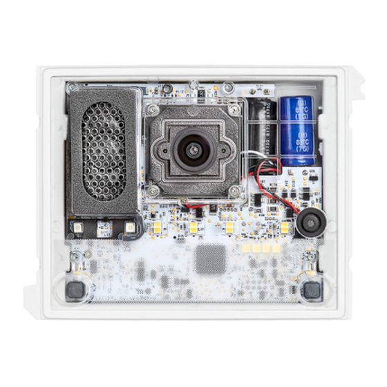
1. INTRODUCTION The device may be used: 1. To make panels with buttons only. – See the information in this booklet for basic programming of the device without WiFi connection. – See § 7 of the booklet for advanced programming of the device with WiFi connection. 2. Paired with display module Ref. 1168/1. – To configure the device implemented in 2VOICE systems, download the relevant instrument booklets from the Urmet website by scanning the following QR Code with the camera of your smartphone or tablet. http://qrcode.urmet.com/default.aspx?prodUrmet=142071&lingua=en 2. DESCRIPTION The audio-video door unit (Ref. 1083/48) and the audio door unit (Ref. 1083/38) are 2VOICE system devices. They have a one-module mod. 1168 mechanical structure and are provided with: • Two calling buttons • System state indication (DDA) • Wide-angle colour camera with LED (Ref. 1083/48 only). 3. STRUCTURE FRONT VIEW Ref. 1083/48 Ref. 1083/38 1. DDA LED (see § 8); The LEDs identify the selected parameter type during configuration. 2. “USER 0” calling button 3. Speaker 4. Name tag and button light LED... -
Page 11: Description Of Terminals
REAR VIEW (IN COMMON TO BOTH MODULES) 11 12 10. Configuration button (PROGRAM); 11. Connector for hearing aid coil (ILA) Ref. 1168/48 12. (*) Trimmer for adjusting speaker volume (RV1) 13. Module connection wire connector (OUT) 14. Label with MAC ADDRESS of the device 15. Jumper provided to connect the door state sensor 16. Terminal board (*) Based on the device version, the trimmer may not be available. In this case, to implement the audio adjustment, refer to the Advanced configuration booklet by scanning the QR Code in the Advanced configuration chapter. -
Page 12: Parameter 4: Call Button Enabling
5.1.3. PARAMETER 3: door opener This is used to manage lock door opener mode; possible options are “Free” or “Privacy”. In “Privacy” mode, the electric lock may only be activated by pressing the door opening button on the calling station when an audio conversation has been established or when after having received a call or auto-on function either a video connection has been established. In “Free” mode, instead, the indoor station door opener button will only open the door unit electrical lock only if the door unit is configured as main or the user belongs to the same door unit riser. This riser is defined by the secondary door unit ID setting. This function is typically used for secondary stations. The above applies to the vehicle and pedestrian gate electrical lock. 5.1.4. PARAMETER 4: call button enabling This parameter can be changed to enable call buttons (2) and (7) present on the front part of the door unit. Specifically, the buttons can be enabled on the call button only (7), on both buttons or on no button. 5.1.5. PARAMETER 5: button enabling to call switchboard If the door unit was configured as main unit (by means of parameter 1), then call buttons (2) and (7) can be enabled to call the switchboard. If the buttons are enabled to call the switchboard (parameter 5 enabled) if will not be possible to configure the call button enabling function (parameter 4). -
Page 13: Parameter Associated To Programming Led (1) Colour
5.4. PARAMETER ASSOCIATED TO PROGRAMMING LED (1) COLOUR Parameter to be configured LED (1) Parameter value LED state (4) Main LEDs off door unit type LED C: Green Parameter 1: Secondary LEDs on steady Address 0 LEDs off door unit ID LED C: Red Parameter 2: Address 1 LEDs on steady Privacy LEDs off Parameter 3: door opener LED B: Orange Free LEDs on steady... -
Page 14: Speaker Volume Adjustment
8. SPEAKER VOLUME ADJUSTMENT Volumes are calibrated by default so not to require adjustments in most cases. Based on the device model, if you need to modify them, use a screwdriver on the volume adjustment trimmer (12) of the speaker. If the trimmer is not present to adjust the volume, please refer to the Advanced Configuration Booklet by scanning the QR Code in the Advanced configuration chapter. 9. DDA (Disability Discrimination Act) LED ACTUATION - SYSTEM STATUS INDICATION The system state is shown by the following indications which appear on the door unit front: a) call in progress: LED... -
Page 15: Connection Example
13. CONNECTION EXAMPLE Rear view of the modules fixed to the panel frame in tipped position. 8 cm/ 3.1” long cord provided with button module with expansion unit Ref. 1168/4 and 1168/8 of the ILA and voice synthesis module Ref. 1168/48 and of the door number module Ref. 1168/50. 82 cm / 32.2” cord provided with ILA and voice synthesis module Ref. 1168/48. 38 cm / 14.9” long cord provided with two-module frame Ref. -
Page 16: Français
FRANÇAIS 1. PREAMBULE ............................17 2. DESCRIPTION ............................17 3. STRUCTURE ............................17 4. DESCRIPTION DES BORNES ....................... 18 5. CONFIGURATION DES PRINCIPAUX PARAMETRES (SANS CONNEXION WiFi) ........ 18 5.1. PARAMETRES CONFIGURABLES ....................18 5.1.1. PARAMETRE 1 : typologie de poste externe ..............18 5.1.2. PARAMETRE 2 : identifiant (ID) du poste externe ............18 5.1.3. PARAMETRE 3 : ouvre-porte .................... -
Page 17: Preambule
1. PREAMBULE Le dispositif peut être utilisé : 1. pour la réalisation de claviers ne comportant que des touches ; – Pour la programmation de base du dispositif sans connexion WiFi, se reporter aux informations contenues dans cette notice. – Pour la programmation avancée du dispositif avec connexion WiFi, se reporter au paragraphe 7 de cette notice. 2. en association avec le module afficheur Réf. 1168/1. – Pour la configuration du dispositif mis en place dans des systèmes 2VOICE, télécharger les notices depuis le site Urmet, en lisant le Code QR suivant à l’aide d’un smartphone ou d’une tablette. http://qrcode.urmet.com/default.aspx?prodUrmet=142071&lingua=en 2. DESCRIPTION Le poste externe audio/vidéo (Réf. 1083/48) et le poste externe audio (Réf. 1083/38) sont réservés au système 2VOICE. Ils sont réalisés à partir de la mécanique mod. 1168 à un module et ils incluent : •... -
Page 18: Description Des Bornes
VUE ARRIERE (COMMUNE AUX DEUX MODULES) 11 12 10. Touche de configuration (PROGRAM) ; 11. Connecteur pour module avec bobine pour malentendants (ILA) Réf. 1168/48; 12. (*) Sélecteur de réglage du volume du haut-parleur (RV1) ; 13. Connecteur pour câble de connexion des modules (OUT) ; 14. Etiquette avec adresse MAC ADDRESS du dispositif ; 15. Cavalier prévu pour le raccordement au capteur d’état porte ; 16. Bornier. (*) Selon la version du dispositif, le trimmer peut ne pas être disponible. Ainsi, pour réaliser le réglage audio, référez-vous au Notice de configuration avancée en scannant le QR Code présent dans le chapitre Configuration avancée. -
Page 19: Parametre 3 : Ouvre-Porte
5.1.3. PARAMETRE 3 : ouvre-porte Permet de gérer le mode ouvre-porte de la serrure électrique, qui peut être “libre” ou “confidentiel”. En mode “confidentiel”, la pression sur touche ouvre-porte du poste interne ne peut activer la serrure électrique du poste d’appel que si le premier a reçu un appel ou est en communication phonique avec le second ou si, suite à une activation automatique, une connexion a été établie. En mode “libre”, la pression sur la touche ouvre-porte d’un poste interne ne peut activer la serrure électrique du poste externe que si celui-ci est configuré comme principal ou si l’utilisateur appartient à la colonne du poste externe secondaire. Cette colonne est définie par la configuration de l’ID du poste externe secondaire. Cette prestation est généralement utilisée sur les postes secondaires. Cela concerne aussi bien la serrure électrique de l’accès véhicules que celle de l’accès piétons. 5.1.4. PARAMETRE 4 : habilitation des touches d’appel La variation de ce paramètre permet d’habiliter les touches d’appel (2) et (7), présentes sur la façade du poste externe. En particulier, l’habilitation des touches peut s’effectuer sur la seule touche d’appel (7), sur les deux touches ou sur aucune des deux. 5.1.5. PARAMETRE 5 : habilitation des touches pour l’appel vers la centrale Si le poste externe a été configuré comme principal (en agissant sur le paramètre 1), il est possible d’habiliter les touches d’appel (2) et (7) pour l’appel vers la centrale. Si l’on décide d’habiliter les touches pour l’appel vers la centrale (paramètre 5 habilité), il ne sera pas possible de configurer l’habilitation des touches d’appel (paramètre 4). -
Page 20: Association Des Parametres Aux Couleurs Des Led (1) De Programmation
5.4. ASSOCIATION DES PARAMETRES AUX COULEURS DES LED (1) DE PROGRAMMATION Paramètre à configurer LED (1) Valeur du paramètre Etat des LED (4) Principal LED éteintes typologie de poste LED C : Vert Paramètre 1: externe Secondaire LED allumées fixes Adresse 0 LED éteintes identifiant (ID) du LED C : Rouge Paramètre 2: poste externe Adresse 1... -
Page 21: Reglage Du Niveau Sonore Du Haut-Parleur
8. REGLAGE DU NIVEAU SONORE DU HAUT-PARLEUR Les niveaux sonores sont réglés en usine et ne doivent pas être modifiés dans la plupart des installations. Selon le modèle du dispositif, s’il est nécessaire de les modifier, utilisez un tournevis pour régler le volume du trimmer (12) de l’enceinte. Si le trimmer n’est pas présent, pour régler le volume, référez-vous au Notice de configuration avancée en scannant le QR Code présent dans le chapitre Configuration avancée. 9. COMMANDE LED DDA (DISABILITY DISCRIMINATION ACT) - INDICATION D’ETAT DE L’INSTALLATION L’état du système est ainsi affiché sur la façade du poste externe : a) appel en cours : LED allumage en vert et message vocal “APPEL EN COURS” ;... -
Page 22: Exemple De Raccordement
13. EXEMPLE DE RACCORDEMENT Vue arrière des modules fixés aux cadres rabattus du clavier. Câble de 8 cm / 3.1” livré avec le module touches avec expansion Réf. 1168/4 et 1168/8, le module ILA et synthèse vocale Réf. 1168/48 et le module n. de rue Réf. 1168/50. Câble de 82 cm / 32.2” livré avec le module ILA et synthèse vocale Réf. 1168/48. Câble de 38 cm / 14.9” livré avec le cadre à 2 modules Réf. 1168/62 et le boîtier avec cadre à 2 modules Réf. 1168/312. -
Page 23: Español
ESPAÑOL 1. PREMISA ............................24 2. DESCRIPCIÓN ............................24 3. ESTRUCTURA ............................24 4. DESCRIPCIÓN DE LOS BORNES ......................25 5. CONFIGURACIÓN DE LOS PARÁMETROS BÁSICOS (SIN UTILIZAR UNA CONEXIÓN WiFi) .... 25 5.1. PARÁMETROS A CONFIGURAR ....................25 5.1.1. PARÁMETRO 1: tipo de microaltavoz ................25 5.1.2. PARÁMETRO 2: identificación (ID) del microaltavoz ............ -
Page 24: Premisa
1. PREMISA El dispositivo se puede utilizar: 1. para la versión de teclados que solo tienen pulsadores; – Para la programación básica del dispositivo sin conexión WiFi seguir la información detallada en este manual. – Para la programación avanzada del dispositivo con conexión WiFi seguir la información presente en el apartado 7 del manual. 2. combinado con el módulo pantalla Ref. 1168/1. – Para la configuración del dispositivo implementado en sistemas 2VOICE, descargar los manuales de instrucciones específicos del sitio Urmet, leyendo el QR Code siguiente con la cámara del smartphone o la tableta. http://qrcode.urmet.com/default.aspx?prodUrmet=142071&lingua=en 2. DESCRIPCIÓN El microaltavoz audio vídeo (Ref. 1083/48) y el audio (Ref. 1083/38) están dedicados al sistema 2VOICE. Están realizados con mecánica mod. 1168 de un módulo y contienen: • Dos pulsadores de llamada; • Indicación del estado del sistema (DDA); • Cámara gran angular de colores y con led de iluminación (solo en Ref. 1083/48). 3. ESTRUCTURA VISTA FRONTAL Ref. 1083/48 Ref. 1083/38 1. Led de visualización del estado DDA (ver el apartado 8); En la fase de configuración, los leds identifican el tipo de parámetro seleccionado. 2. Pulsador de llamada “USUARIO 0”;... -
Page 25: Descripción De Los Bornes
VISTA TRASERA (EN COMÚN PARA LOS DOS MÓDULOS) 11 12 10. Pulsador de configuración (PROGRAM); 11. Conector para módulo con bobina para hipoacúsicos (ILA) Ref. 1168/48; 12. (*) Trimmer para la regulación del volumen del altavoz (RV1); 13. Conector para el cable de conexión de módulos (OUT); 14. Etiqueta con la dirección MAC ADDRESS del dispositivo. 15. Puente previsto para la conexión al sensor de estado de la puerta; 16. Tablero de bornes; (*) Dependiendo de la versión del dispositivo, es posible que el trimmer no esté disponible. En este caso, para realizar el ajuste de audio, remitirse al Manual de configuración avanzada escaneando el Código QR presente en el cap. -
Page 26: Parámetro 3: Apertura De La Puerta
5.1.3. PARÁMETRO 3: apertura de la puerta Permite gestionar el modo de apertura de la puerta de la cerradura eléctrica, que puede ser “libre” o “con secreto”. En el modo “Con secreto”, el accionamiento del pulsador de apertura de la puerta del aparato interior puede activar la cerradura eléctrica del puesto de llamada solo si recibió una llamada o se encuentra en conversación fónica con la misma, o también, si después de una autoactivación, está en conexión con la misma. En cambio, en el modo “Libre” el accionamiento del pulsador de apertura de la puerta de un aparato interior puede activar la cerradura eléctrica del microaltavoz solo si el mismo está configurado como principal o si el usuario pertenece a la columna del mismo microaltavoz secundario. Esa columna está definida por la configuración del ID del microaltavoz secundario. La función se utiliza normalmente en los puestos secundarios. -
Page 27: Asociación Del Parámetro Al Color De Los Leds (1) De Programación
5.4. ASOCIACIÓN DEL PARÁMETRO AL COLOR DE LOS LEDS (1) DE PROGRAMACIÓN Parámetro a configurar LED (1) Valor del parámetro Estado de los LEDs (4) Principal Leds apagados tipo de microaltavoz Led C: Verde Parámetro 1: Secundario Leds encendidos fijos Dirección 0 Leds apagados identificación (ID) del Led C: Rojo Parámetro 2: microaltavoz... -
Page 28: Regulación Del Nivel Fónico Del Altavoz
8. REGULACIÓN DEL NIVEL FÓNICO DEL ALTAVOZ Los niveles fónicos están calibrados de fábrica para no tener que modificarlos en la mayor parte de las instalaciones. Dependiendo del modelo del dispositivo, si fuera necesario modificarlos, actuar con un destornillador sobre el trimmer de ajuste del volumen (12) del altavoz, si el trimmer no está presente para realizar el ajuste del volumen, remitirse al Manual de configuración avanzada escaneando el Código QR presente en el cap. Configuración avanzada. 9. ACCIONAMIENTO DEL LED DDA (DISABILITY DISCRIMINATION ACT) - INDICACIÓN DE ESTADO DEL SISTEMA El estado del sistema se indica con las siguientes señales, que se pueden ver en la placa del microaltavoz: a) llamada en curso: led encendido de color verde y mensaje de voz “LLAMANDO”;... -
Page 29: Ejemplo De Conexión
13. EJEMPLO DE CONEXIÓN Vista trasera de los módulos fijados en los marcos del teclado volteados. Cable de 8 cm / 3.1” de longitud entregado con el módulo de pulsadores con expansor Ref. 1168/4 y 1168/8, del módulo ILA y de síntesis vocal Ref. 1168/48, y del módulo para el número del edificio Ref. 1168/50. Cable de 82 cm / 32.2” de longitud entregado con el módulo ILA y de síntesis vocal Ref. 1168/48. Cable de 38 cm / 14.9” de longitud entregado con el marco para 2 módulos Ref. 1168/62 y de la cubierta con marco de 2 módulos Ref. 1168/312. -
Page 30: Deutsch
DEUTSCH 1. VORBEMERKUNG ..........................31 2. BESCHREIBUNG ........................... 31 3. STRUKTUR ............................31 4. BESCHREIBUNG DER ANSCHLUSSKLEMMEN .................. 32 5. KONFIGURATION WESENTLICHER PARAMETER (OHNE EINSATZ EINER WI-FI- VERBINDUNG) ... 32 5.1. KONFIGURIERBARE PARAMETER ..................... 32 5.1.1. PARAMETER 1: Typ der Außenstelle ................32 5.1.2. PARAMETER 2: Identifizierung (ID) der Außenstelle ............32 5.1.3. PARAMETER 3: Türöffner .................... -
Page 31: Vorbemerkung
1. VORBEMERKUNG Das Gerät kann eingesetzt werden für: 1. die Einrichtung von Tastenfeldern, die nur Tasten umfassen; – Für die Basisprogrammierung des Geräts ohne Wi-Fi-Verbindung die in dieser Anleitung enthaltenen Informationen beachten. – Für die Basisprogrammierung des Geräts mit Wi-Fi-Verbindung die Informationen unter Abs. 7 der Anleitung beachten. 2. in Kombination mit dem Display-Modul BN 1168/1. – Für die Konfiguration des in die 2VOICE-Systeme implementierten Geräts die jeweiligen Bedienungsanleitungen von der Website von Urmet herunterladen und dazu den folgenden QR-Code mit der Kamera Ihres Smartphones oder Tablets ablesen. http://qrcode.urmet.com/default.aspx?prodUrmet=142071&lingua=en 2. BESCHREIBUNG Die Audio-/Video-Außenstelle (BN 1083/48) und die Audio-Außenstelle (BN 1083/38) sind speziell für das 2VOICE-System ausgelegt. Sie sind auf der Mechanik des Mod. 1168 mit einem Modul eingerichtet und sehen Folgendes vor: • Zwei Ruftasten; • Anzeige des Anlagenstatus (DDA); • Weitwinkel-Kamera in Farbe und mit Beleuchtungs-Leds (nur auf BN 1083/48). 3. -
Page 32: Beschreibung Der Anschlussklemmen
RÜCKANSICHT (FÜR BEIDE MODULE GLEICH) 11 12 10. Konfigurationstaste (PROGRAM); 11. Verbinder für Modul mit Spule für Hörbehinderte (ILA) BN 1168/48; 12. (*) Trimmer zur Regulierung der Lautsprecherlautstärke (RV1); 13. Verbinder für das Modul-Anschlusskabel (OUT); 14. Etikett mit Adresse (MAC ADDRESS) des Geräts. 15. Brücke für den Anschluss an den Statussensor des Ports; 16. Klemmenleiste. (*) Je nach Geräteversion ist der Trimmer möglicherweise nicht verfügbar. In diesem Fall lesen Sie bitte das Handbuch zur erweiterten Konfiguration, indem Sie den QR-Code unter „Erweiterte Konfiguration“ scannen. -
Page 33: Parameter 3: Türöffner
5.1.3. PARAMETER 3: Türöffner Gestattet die Steuerung des Türöffnermodus der Elektroverrieglung, die „frei“ oder „geheim“ sein kann. Im Modus „Geheim“ kann das Betätigen der Türöffnertaste der Innenstelle die Elektroverriegelung der Rufeinheit nur aktivieren, wenn diese einen Anruf erhalten hat oder sich im Gespräch damit befindet oder auch, wenn im Anschluss an eine Selbsteinschaltung in jedem Fall eine Verbindung damit vorliegt. Im Modus „Frei“ dagegen kann das Betätigen der Türöffnertaste einer Innenstelle die Elektroverriegelung der Außenstelle nur aktivieren, wenn diese als Hauptstelle konfiguriert ist oder der Teilnehmer zur Steigleitung derselben Nebenaußenstelle gehört. Diese Steigleitung wird durch die Eingabe der ID der Nebenaußenstelle definiert. Dieses Merkmal wird normalerweise auf Nebenstellen eingesetzt. Wenn sie angegeben ist, gilt sie sowohl für die Elektroverriegelung der Zufahrt als auch für die des Fußgänger-Eingangs. -
Page 34: Zuordnung Des Parameters Zur Farbe Der Leds (1) Der Programmierung
5.4. ZUORDNUNG DES PARAMETERS ZUR FARBE DER LEDS (1) DER PROGRAMMIERUNG Zu konfigurierender Parameter LED (1) Wert des Parameters Status der LEDs (4) Haupt- Led ausgeschaltet Led C: Parameter 1: Typ der Außenstelle Grün Neben- Leds durchgehend eingeschaltet Adresse 0 Led ausgeschaltet Led C: Identifizierung (ID) Parameter 2: der Außenstelle Adresse 1 Leds durchgehend eingeschaltet Mithörsperre Led ausgeschaltet... -
Page 35: Einstellung Der Gesprächslautstärke Des Lautsprechers
8. EINSTELLUNG DER GESPRÄCHSLAUTSTÄRKE DES LAUTSPRECHERS Die Gesprächslautstärken werden werkseitig geeicht, um in der Mehrzahl der Installationen nicht geändert werden zu müssen. Sollte es je nach Gerätemodell notwendig sein, diese zu ändern, verwenden Sie einen Schraubendreher am Lautstärkeregulierungstrimmer (12) des Lautsprechers. Sollte der Trimmer nicht vorhanden sein, um die Lautstärke einzustellen, lesen Sie bitte das Handbuch zur erweiterte Konfiguration, indem Sie den QR-Code im Kapitel „Erweiterte Konfiguration“ scannen. -
Page 36: Anschluss Beispiel
13. ANSCHLUSS BEISPIEL Rückansicht der an den Rahmen der gekippten Tastenfelder befestigten Module. langes Kabel Lieferumfang des Tastenmoduls mit Erweiterung B/N 1168/4 1168/8 ILA- Sprachsynthesemoduls 1168/48 und des Hausnummern- Moduls B/N 1168/50. langes Kabel Lieferumfang des ILA- und Sprachsynthesemoduls B/N 1168/48. langes Kabel Lieferumfang des Rahmens mit 2 Modulen B/N 1168/62 und des Gehäuses mit Rahmen mit 2 Modulen BN 1168/312. langes Kabel Lieferumfang des Rahmens mit... -
Page 37: Nederlands
NEDERLANDS 1. VOORWOORD ............................38 2. BESCHRIJVING ............................. 38 3. CONSTRUCTIE ............................38 4. BESCHRIJVING VAN DE KLEMMENBORDEN ..................39 5. CONFIGURATIE BASISPARAMETERS (ZONDER WiFi-VERBINDING)..........39 5.1. CONFIGUREERBARE PARAMETERS ..................39 5.1.1. PARAMETER 1: type buitenpost ..................39 5.1.2. PARAMETER 2: identificatie (ID) van de buitenpost ............39 5.1.3. -
Page 38: Voorwoord
1. VOORWOORD Het apparaat kan worden gebruikt: 1. om deurplaten te vervaardigen met uitsluitend toetsen; – Voor de basisprogrammering van het apparaat zonder WiFi-verbinding de informatie in deze handleiding volgen. – Voor de geavanceerde programmering van het apparaat met WiFi-verbinding de informatie in paragraaf 7 van de handleiding volgen. 2. in combinatie met de display-module Sch. 1168/1. – Voor de configuratie van het apparaat dat wordt opgenomen in 2VOICE-systemen downloadt u de bijbehorende handleidingen met gebruiksaanwijzingen op de site van Urmet met de volgende QR Code met behulp van de camera van uw smartphone of tablet. -
Page 39: Beschrijving Van De Klemmenborden
ACHTERAANZICHT (GEMEENSCHAPPELIJK VOOR BEIDE MODULES) 11 12 10. Configuratietoets (PROGRAM); 11. Connector voor de module met spoel voor slechthorenden (ILA) Sch. 1168/48; 12. (*) Trimmer om het volume van de luidspreker te regelen (RV1); 13. Connector voor de aansluitkabel van de modules (OUT); 14. Etiket met het MAC ADRES van het apparaat. 15. Brug voor de verbinding met de deurstatussensor; 16. Aansluitklemmenbord. (*) De trimmer is mogelijk niet beschikbaar naargelang de versie van het apparaat. Raadpleeg in dit geval het boekje Geavanceerde configuratie door de QR-code in het hoofdstuk Geavanceerde configuratie te scannen om de geluidsregeling uit te voeren. -
Page 40: Parameter 3: Deuropener
5.1.3. PARAMETER 3: deuropener Om de deuropener van het elektrisch slot in te stellen op “vrij” of “geheim”. In de configuratie “Geheim” kan het indrukken van de deuropenertoets het elektrisch slot alleen openen met de oproeppost als deze een oproep heeft ontvangen of er een gesprek mee aan het voeren is of er hoe dan ook mee is verbonden na een automatische inschakeling. In de configuratie “Vrij” kan met het indrukken van de deuropenertoets op een binnenpost het elektrisch slot van de buitenpost alleen openen als deze geconfigureerd is als hoofdbuitenpost of als de gebruiker tot de kolom behoort van dezelfde secundaire buitenpost. Deze kolom wordt bepaald door de configuratie van het ID van de secundaire buitenpost. Deze functie wordt meestal op de secundaire posten gebruikt. Wat vermeld is, geldt zowel voor het elektrisch slot van de inrijpoort als dat van de voetgangersingang. 5.1.4. PARAMETER 4: inschakeling oproeptoetsen Een variatie van deze parameter kan de oproeptoetsen (2) en (7) op de voorkant van de buitenpost inschakelen. Zowel alleen de oproeptoets(7), als beide, als geen enkele toets kan worden ingeschakeld. 5.1.5. PARAMETER 5: vrijgave van de toetsen voor oproep van centrale Als de buitenpost geconfigureerd is als hoofdpost (met parameter 1) kunnen de oproeptoetsen (2) en (7) worden vrijgegeven om de centrale op te roepen. Als u beslist om de toetsen vrij te geven voor oproepen aan de centrale (Parameter 5 ingeschakeld) kunt u de toetsen niet meer vrijgeven om als oproeptoetsen (Parameter 4). -
Page 41: Parameter Combineren Met Kleur Van Programmeer-Leds (1)
5.4. PARAMETER COMBINEREN MET KLEUR VAN PROGRAMMEER-LEDS (1) Waarde van de Status van de LEDS Te configureren parameter LED (1) parameter Hoofdpost Leds uit type buitenpost Led C: Groen Parameter 1: Secundaire post Leds branden continu Adres 0 Leds uit identificatie (ID) van Led C: Rood Parameter 2: de buitenpost Adres 1 Leds branden continu Geheim Leds uit Parameter 3: deuropener Led B: Oranje... -
Page 42: Volumeregeling Luidspreker
8. VOLUMEREGELING LUIDSPREKER De geluidsvolumes zijn per fabriek zodanig ingesteld dat ze meestal niet moeten worden gewijzigd tijdens de installatie. Als een wijziging is vereist, gebruik dan een schroevendraaier voor de trimmer van de volumeregeling (12) van de luidspreker, , als de trimmer niet aanwezig is, raadpleeg dan het boekje Geavanceerde configuratie door de QR-code in het hoofdstuk Geavanceerde configuratie te scannen. -
Page 43: Voorbeeld Van Aansluiting
13. VOORBEELD VAN AANSLUITING Achteraanzicht van de modules bevestigd op de gekantelde frames van de deurplaat. 8 cm lang kabeltje, meegeleverd met de toetsenmodule met uitbreiding Sch. 1168/4 en 1168/8, van de module ILA en de voice-module Sch. 1168/48 en de huisnummermodule Sch. 1168/50. Kabeltje van 82 cm dat bij de ILA-module en voice-module Sch. 1168/48 hoort. Kabeltje van 38 cm bij het frame 2 modules Sch. 1168/62 en de houder met frame met 2... - Page 44 ENGLISH Contain module with FCC ID 2AC7Z-ESPWROOM02 15.105 Information to the user statements: This equipment has been tested and found to comply with the limits for a Class B digital device, pursuant to part 15 of the FCC Rules. These limits are designed to provide reasonable protection against harmful interference in a residential installation. This equipment generates, uses and can radiate radio frequency energy and, if not installed and used in accordance with the instructions, may cause harmful interference to radio communications. However, there is no guarantee that interference will not occur in a particular installation. If this equipment does cause harmful interference to radio or television reception, which can be determined by turning the equipment off and on, the user is encouraged to try to correct the interference by one or more of the following measures: ― Reorient or relocate the receiving antenna. ― Increase the separation between the equipment and receiver. ― Connect the equipment into an outlet on a circuit different from that to which the receiver is connected.
- Page 45 ESPAÑOL Contenedor de módulo con FCC ID 2AC7Z-ESPWROOM02 15.105 Información a las declaraciones de usuario : Este equipo ha sido sometido a las pruebas pertinentes y cumple con los límites establecidos para un dispositivo digital de Clase B, conforme al apartado 15 de las reglas de la FCC. Estos límites están diseñados para proporcionar una protección razonable contra la interferencia dañina en una instalación residencial. Este equipo genera, utiliza y puede irradiar energía de radiofrecuencia y si no se instala y utiliza de acuerdo con las instrucciones, puede causar interferencias perjudiciales en las comunicaciones de radio. Sin embargo, no hay garantía de que no se vaya a producir interferencia en una instalación en específico. Si este equipo causa interferencia perjudicial a la recepción de radio o televisión, puede determinarla prendiendo y apagando el equipo, se recomienda al usuario que intente corregir la interferencia realizando una o más de las siguientes medidas: ― Cambie la orientación o ubicación de la antena receptora. ― Aumente la distancia entre el equipo y el receptor. ― Conecte el equipo a la toma corriente en un circuito distinto al que esté conectado el receptor. ― Consulte al distribuidor o a un técnico de radio y TV con experiencia. Aviso de advertencia de la exposición de RF Para seguir los requisitos de conformidad de exposición a las RF de la FCC, se debe mantener la distancia de separación de al menos 20 cm entre la antena de este dispositivo y todas las personas cercanas. Los cambios o modificaciones no aprobados expresamente por la parte responsable del cumplimiento pueden anular la autoridad del usuario para utilizar el equipo. DS1083-180...
- Page 46 ITALIANO DIRETTIVA 2012/19/UE DEL PARLAMENTO EUROPEO E DEL CONSIGLIO del 4 luglio 2012 sui rifiuti di apparecchiature elettriche ed elettroniche (RAEE) Il simbolo del cassonetto barrato riportato sull’apparecchiatura o sulla sua confezione indica che il prodotto alla fine della propria vita utile deve essere raccolto separatamente dagli altri rifiuti. L’utente dovrà, pertanto, conferire l’apparecchiatura giunta a fine vita agli idonei centri comunali di raccolta differenziata dei rifiuti elettrotecnici ed elettronici. In alternativa alla gestione autonoma è possibile consegnare l’apparecchiatura che si desidera smaltire al rivenditore, al momento dell’acquisto di una nuova...
- Page 47 DEUTSCH RICHTLINIE 2012/19/EU DES EUROPÄISCHEN PARLAMENTS UND DES RATES VOM 4. Juli 2012 über Elektro- und Elektronik-Altgeräte (WEEE) Das Symbol der durchgestrichenen Abfalltonne auf Rädern auf dem Produkt oder dessen Verpackung gibt an, dass das Produkt nicht zusammen mit dem Hausmüll entsorgt werden darf. Es liegt daher in Ihrer Verantwortung, Ihre Altgeräte zu entsorgen, indem Sie diese bei einer geeigneten Sammelstelle für das Recycling für Elektro- und Elektronik-Altgeräte abgeben. Die getrennte Sammlung und das Recycling Ihrer Altgeräte bei der Entsorgung tragen zur Erhaltung natürlicher Ressourcen bei und garantieren, dass diese auf gesundheits- und umweltverträgliche Weise recycelt werden Weitere Informationen dazu, wo Sie Ihre Altgeräte zum Recycling abgeben können, erhalten Sie bei Ihrer Gemeindeverwaltung, Ihrem Hausmüll- Entsorgungsdienst oder bei dem Händler, bei dem Sie das Produkt gekauft haben. NEDERLANDS RICHTLIJN 2012/19/EU VAN HET EUROPEES PARLEMENT EN DE RAAD van 4 juli 2012 betreffende afgedankte elektrische en elektronische apparatuur (AEEA) Het symbool van een doorgekruiste verrijdbare afvalbak op het product of op de verpakking ervan betekent dat dit product niet samen met ander stedelijk afval mag worden verwijderd. Het is uw...
- Page 48 DS 1083-180 LBT 21403 URMET S.p.A. Area tecnica 10154 TORINO (ITALY) servizio clienti +39 011.23.39.810 VIA BOLOGNA 188/C http://www.urmet.com Telef. +39 011.24.00.000 (RIC. AUT.) e-mail: info@urmet.com +39 011.24.00.300 - 323 MADE IN ITALY...
Need help?
Do you have a question about the 2VOICE 1083/48 and is the answer not in the manual?
Questions and answers