
Related Manuals for SIGMATEK SAI 041


Summary of Contents for SIGMATEK SAI 041
- Page 1 SAI 041 S-DIAS Safety Analog Input Current Module Operating Manual Date of creation: 28.04.2022 Version date: 18.05.2022 Article number: 20-896-041-E...
- Page 2 (print, photocopy, microfilm or in any other process) without express permission. We reserve the right to make changes in the content without notice. SIGMATEK GmbH & Co KG is not responsible for technical or printing errors in this handbook and assumes no responsibility for damages that occur through its use.
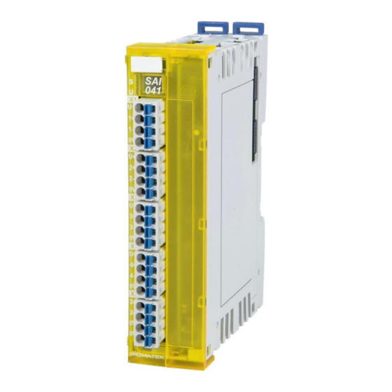
- Page 3 SAFETY ANALOG INPUT CURRENT MODULE SAI 041 S-DIAS Safety Analog-Input Current Module SAI 041 The S-DIAS safety analog input module provides the values of four analog current inputs from the Safe CPU (Safety CPU). The analog inputs can also be read by the functional control CPU via the S-DIAS bus from the safety CPU.
-
Page 4: Table Of Contents
SAI 041 SAFETY ANALOG INPUT CURRENT MODULE Table of Contents Basic Safety Guidelines ............4 General Information on Safety ............ 4 Further Safety Guidelines ............5 General Requirements ..............6 Safety Conformity ..............8 Functional Safety Standards ............8 EU Conformity Declaration ............8 Safety-Relevant Parameters ............ - Page 5 SAFETY ANALOG INPUT CURRENT MODULE SAI 041 Wiring ..................19 Wiring Example 1 SIL 3 Sensor ..........19 Connection Example: 2 SIL 2 Sensors ........20 Connecting a 2-Wire Sensor ............21 Connecting a 3-wire Sensor ............21 Connecting a 4-Wire Sensor ............22 Wiring Example Terminating Open Inputs .......
-
Page 6: Basic Safety Guidelines
SAI 041 SAFETY ANALOG INPUT CURRENT MODULE Basic Safety Guidelines General Information on Safety If the Safety guidelines are not followed, danger to personnel can result, which could then lead to serious injury or in worst cases, death. In less serious cases, systems and equipment can be damaged. -
Page 7: Further Safety Guidelines
SAFETY ANALOG INPUT CURRENT MODULE SAI 041 Further Safety Guidelines Danger for ESD-sensitive components. Les signes de danger pour les composants sensibles aux décharges électrostatiques. This symbol identifies important additional information regarding the operation of the safety modules. 18.05.2022 Page 5... -
Page 8: General Requirements
Before handling the product to which this documentation Guidelines belongs, the operating instructions and safety guidelines must be read. SIGMATEK GmbH & Co KG accepts no liability for damages resulting from non-compliance with the Safety guidelines or the applicable regulations. - Page 9 SAFETY ANALOG INPUT CURRENT MODULE SAI 041 Designated Use The Safety modules are designed for use in safety-oriented applications and meet the required conditions for safety operation in compliance with Performancelevel e (PL e) CAT4 in accordance with EN ISO 13849-1/-2 and SIL 3 in accordance with EN 62061.
-
Page 10: Safety Conformity
EN ISO 13849-2 EU Conformity Declaration EU Conformity Declaration The SAI 041 conforms to the following European guidelines: • 2006/42/EG “Directive of the European Parliament and of the Council of 17 May 2006 on Machinery and Change to the Directive 95/16/EC”... -
Page 11: Safety-Relevant Parameters
The application for a specific PL, These safety parameters were calculated category or SIL requires a risk analysis of for the SAI 041 using sensor The Safety the end application, which for example, parameters of the entire machine must determines whether two sensors are be determined in the end application. -
Page 12: Technical Data
SAI 041 SAFETY ANALOG INPUT CURRENT MODULE Technical Data Analog Input Specifications Number of channels Measurement range 4-20 mA Measurement value 12,000-60,000 Measurement range Overrange 0.5-21.6 mA and Under range Measurement range Overrange 1500-64,800 and Under range Input type differential input... -
Page 13: Measurement Range
SAI 041 Measurement Range The diagram shown below shows the configuration of the SAI 041’s measurement range. The measurement range is configured to 4-20 mA by default. In the Safety Designer, the measurement range can be expanded from 0.5-21.6 mA. Input currents< 0.5mA or > 21.6 mA trigger a safety error. - Page 14 SAI 041 SAFETY ANALOG INPUT CURRENT MODULE The SAI 041 is currently not supported by the SCP 111. When used in combination with an SAI 041, the Safety CPU must be supplied with at least 19.2 V! Page 12 18.05.2022...
- Page 15 SAFETY ANALOG INPUT CURRENT MODULE SAI 041 18.05.2022 Page 13...
-
Page 16: Miscellaneous
SAI 041 SAFETY ANALOG INPUT CURRENT MODULE Miscellaneous Article number 20-897-041 Hardware version Approvals CE, TÜV EG type tested Environmental Conditions Storage temperature -40 ... +85°C Environmental temperature 0 ... +60 °C Humidity 0-95 %, non-condensing Installation altitude above sea... -
Page 17: Mechanical Dimensions
SAFETY ANALOG INPUT CURRENT MODULE SAI 041 Mechanical Dimensions 18.05.2022 Page 15... -
Page 18: Connector Layout
SAI 041 SAFETY ANALOG INPUT CURRENT MODULE Connector Layout The connections of the +24 V supply (X5: pin 1 and pin 2) or the GND supply (X5: pin 3 and pin 4) are internally bridged. To supply the module, only one connection to a +24 V pin (pin 1 or pin 2) and a GND pin (pin 3 or pin 4) is required. -
Page 19: Status Leds
SAFETY ANALOG INPUT CURRENT MODULE SAI 041 Status LEDs Bus status green bus communication OK no supply available BLINKING (5 Hz) no communication Safety Used yellow module is used and no errors exist module is not used or not in operational mode... -
Page 20: Applicable Connectors
SAI 041 SAFETY ANALOG INPUT CURRENT MODULE Applicable Connectors Connectors: X1-X5: Connectors with spring terminals (included with delivery) The spring terminals are suitable for the connection of ultrasonically compressed (ultrasonically welded) strands. Connections: Stripping length/sleeve length: 10 mm Mating direction:... -
Page 21: Wiring
SAFETY ANALOG INPUT CURRENT MODULE SAI 041 Wiring Wiring Example 1 SIL 3 Sensor 1 SIL 3 Sensor: max. achievable level SIL3, PL e, Cat. 3 In order to achieve the desired safety level SIL 3, PL e, Cat. 3, the sensor must have the corresponding properties. -
Page 22: Connection Example: 2 Sil 2 Sensors
SAI 041 SAFETY ANALOG INPUT CURRENT MODULE Connection Example: 2 SIL 2 Sensors Combination of 2 SIL 2 sensors: max. achievable level SIL3 PL e Cat. 4 In order to achieve the desired safety level SIL 3, PL e, Cat. 4, the sensor must have the corresponding properties. -
Page 23: Connecting A 2-Wire Sensor
SAFETY ANALOG INPUT CURRENT MODULE SAI 041 Connecting a 2-Wire Sensor with external +24 V sensor supply with internal sensor supply Connecting a 3-wire Sensor with external +24 V sensor supply with internal sensor supply 18.05.2022 Page 21... -
Page 24: Connecting A 4-Wire Sensor
SAI 041 SAFETY ANALOG INPUT CURRENT MODULE Connecting a 4-Wire Sensor with external +24 V sensor supply with internal sensor supply Wiring Example Terminating Open Inputs The cable-break monitor of the analog input is active as soon as the corresponding channel is activated in the Safety Designer. -
Page 25: Note
SAFETY ANALOG INPUT CURRENT MODULE SAI 041 Note To ensure error-free operation, a careful wiring method must be followed: • The 0 V connection of the supply voltage must be connected with the 0 V collection point over the shortest route possible. -
Page 26: Mounting
SAI 041 SAFETY ANALOG INPUT CURRENT MODULE Mounting The S-DIAS modules are designed for installation into the control cabinet. To mount the modules, a DIN-rail is required. The DIN rail must establish a conductive connection with the back wall of the control cabinet. The individual S-DIAS modules are mounted on the DIN rail as a block and secured with latches. - Page 27 SAFETY ANALOG INPUT CURRENT MODULE SAI 041 Recommended minimum distances between the S-DIAS modules and the surrounding components or control cabinet wall: a, b, c … distances in mm (inches) 18.05.2022 Page 25...
-
Page 28: Transport/Storage
SAI 041 SAFETY ANALOG INPUT CURRENT MODULE Transport/Storage This device contains sensitive electronics. During transport and storage, high mechanical stress must therefore be avoided. For storage and transport, the same values for humidity and vibration as for operation must be maintained! During transport, temperature and humidity fluctuations may occur. -
Page 29: Maintenance
SAFETY ANALOG INPUT CURRENT MODULE SAI 041 11 Maintenance During maintenance as well as servicing, observe the safety instructions from chapter 1. 11.1 Maintenance This product was constructed for low-maintenance operation. 11.2 Repair When sent for repair, the panel should be transported in the original packaging if possible. -
Page 30: Disposal
SAI 041 SAFETY ANALOG INPUT CURRENT MODULE 12 Disposal Should you need to dispose of the device, the national electronic scrap regulation must be observed. The panel cannot be discarded with domestic waste. Page 28 18.05.2022... - Page 31 SAFETY ANALOG INPUT CURRENT MODULE SAI 041 Documentation Changes Change date Affected page(s) Chapter Note 05.05.2022 6 Wiring First two graphics changed and note added 18.05.2022 3.3 Electrical Removed hint SPC as master Requirements 1oo1, 1oo2 evaluation removed 2.3.1 Horizontal...
- Page 32 SAI 041 SAFETY ANALOG INPUT CURRENT MODULE Page 30 18.05.2022...
Need help?
Do you have a question about the SAI 041 and is the answer not in the manual?
Questions and answers