Table of Contents
Advertisement
Quick Links
Advertisement
Table of Contents

Related Manuals for DFI AR100-DR


Summary of Contents for DFI AR100-DR
- Page 1 AR100-DR System Board User’s Manual 935-AR1001-000G A13600006...
-
Page 2: Copyright
Copyright This publication contains information that is protected by copyright. No part of it may be reproduced in any form or by any means or used to make any transfor- mation/adaptation without the prior written permission from the copyright hold- ers. -
Page 3: Fcc And Doc Statement On Class B
FCC and DOC Statement on Class B This equipment has been tested and found to comply with the limits for a Class B digital device, pursuant to Part 15 of the FCC rules. These limits are designed to provide reasonable protection against harmful interference when the equipment is operated in a residential installation. -
Page 4: Table Of Contents
Table of Contents Copyright ................... 2 Trademarks ..................2 FCC and DOC Statement on Class B ..........3 About this Manual ................6 Warranty ..................6 Static Electricity Precautions ............. 7 Safety Measures ................. 7 About the Package ................8 Before Using the System Board ............ - Page 5 Internal I/O Connectors ..............35 S/PDIF-out Connector ............... 35 SATA (Serial ATA) Connectors ............ 36 Cooling Fan Connectors ............. 37 Chassis Instrusion Connector ............. 38 Power Connectors ..............39 Standby Power LED ..............41 Front Panel Connectors ............. 42 Expansion Slot ................. 43 Battery ...................
-
Page 6: About This Manual
Introduction About this Manual An electronic file of this manual is included in the CD. To view the user’s manual in the CD, insert the CD into a CD-ROM drive. The autorun screen (Main Board Utility CD) will appear. Click “User’s Manual” on the main menu. Warranty 1. -
Page 7: Static Electricity Precautions
Introduction Static Electricity Precautions It is quite easy to inadvertently damage your PC, system board, components or devices even before installing them in your system unit. Static electrical dis- charge can damage computer components without causing any signs of physical damage. -
Page 8: About The Package
Introduction About the Package The system board package contains the following items. If any of these items are missing or damaged, please contact your dealer or sales representative for as- sistance. One system board One USB cable One Serial ATA data cable ... -
Page 9: Chapter 1 - Introduction
Introduction Chapter 1 - Introduction Specifications Processor • Socket 940 AM2+ 65nm for: - AMD AM2 processors: Athlon series / Sempron ® - AMD AM3 processors ® • Supports maximum of 65W power CPUs • HyperTransport 3.0 Chipset • AMD chipset ® - Northbridge: AMD RS780E ® - Southbridge: AMD SB710 ®... - Page 10 Introduction Rear Panel I/O • 1 mini-DIN-6 PS/2 mouse port • 1 mini-DIN-6 PS/2 keyboard port • 1 DB-9 serial port • 1 HDMI port • 1 DB-15 VGA port • 1 DVI-I port (DVI-D signal only) • 2 RJ45 LAN ports • 4 USB 2.0/1.1 ports • Mic-in, line-in and line-out Internal I/O • 2 connectors for 4 additional external USB 2.0/1.1 ports • 1 connector for an external serial port • 1 front audio connector for line-out and mic-in jacks • 1 S/PDIF-out connector • 4 Serial ATA connectors • 1 20-pin ATX power connector • 1 4-pin 12V power connector • 1 front panel connector • 1 chassis intrusion connector • 2 fan connectors Energy Efficient • ACPI specification 2.0 compliant power management Design schemes • Supports S1 and S3 • Wake-On-Events include: - Wake-On-PS/2 KB/Mouse - Wake-On-USB KB/Mouse - Wake-On-LAN - Wake-On-Ring - RTC timer to power-on the system...
-
Page 11: Features
Introduction Features DDR2 DDR2 is a higher performance DDR technology whose data transfer rate delivers bandwidth of 4.3 GB per second and beyond. That is twice the speed of the con- ventional DDR without increasing its power consumption. DDR2 SDRAM modules work at 1.8V supply compared to 2.6V memory voltage for DDR modules. DDR2 also incorporates new innovations such as the On-Die Termination (ODT) as well as larger 4-bit pre-fetch against DDR which fetches 2 bits per clock cycle. - Page 12 Introduction Serial ATA with RAID Serial ATA is a storage interface that is compliant with SATA 1.0 specification. It supports speed of up to 3Gb/s. Serial ATA improves hard drive performance faster than the standard parallel ATA whose data transfer rate is 100MB/s. The system board allows configuring RAID on Serial ATA devices.
-
Page 13: Chapter 2 - Hardware Installation
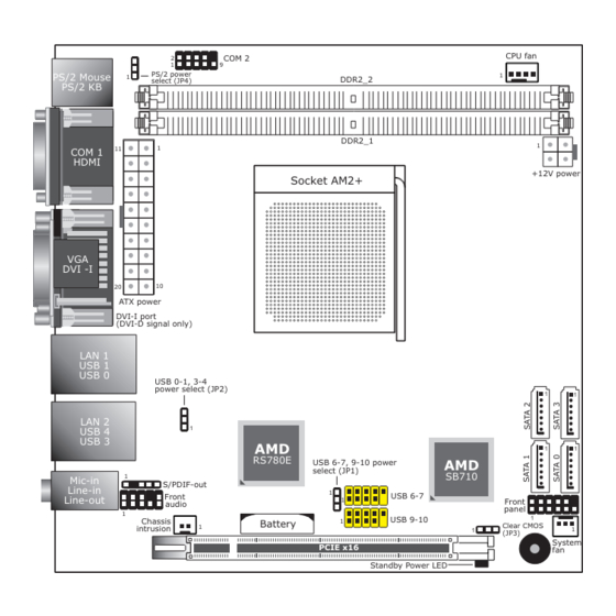
Hardware Installation Chapter 2 - Hardware Installation System Board Layout CPU fan COM 2 PS/2 power PS/2 Mouse DDR2_2 select (JP4) PS/2 KB DDR2_1 COM 1 HDMI +12V power Socket AM2+ DVI -I ATX power DVI-I port (DVI-D signal only) LAN 1 USB 1 USB 0... -
Page 14: System Memory
Hardware Installation Important: Electrostatic discharge (ESD) can damage your system board, processor, disk drives, add-in boards, and other components. Perform the upgrade instruction procedures described at an ESD workstation only. If such a station is not available, you can provide some ESD protection by wearing an antistatic wrist strap and attaching it to a metal part of the system chassis. -
Page 15: Installing The Dim Module
Hardware Installation Installing the DIM Module Note: The system board used in the following illustrations may not resemble the actual board. These illustrations are for reference only. 1. Make sure the PC and all other peripheral devices connected to it has been powered down. - Page 16 Hardware Installation 6. Grasping the module by its edges, position the module above the socket with the “notch” in the module aligned with the “key” on the socket. The keying mechanism ensures the module can be plugged into the socket in only one way.
-
Page 17: Cpu
Hardware Installation Overview The system board is equipped with Socket AM2+ for installing an AMD CPU de- signed for this socket. Installing the CPU 1. Make sure the PC and all other peripheral devices connected to it has been powered down. 2. - Page 18 Hardware Installation 5. Position the CPU above the socket. The gold mark on the CPU must align with pin 1 of the CPU socket. Important: Gold Handle the CPU by its edg- mark es and avoid touching the pins. 6. Insert the CPU into the socket until it is seated in place. The CPU will fit in only one orientation and...
-
Page 19: Installing The Fan And Heat Sink
Hardware Installation Installing the Fan and Heat Sink The CPU must be kept cool by using a CPU fan with heat sink. Without sufficient air circulation across the CPU and heat sink, the CPU will overheat damaging both the CPU and system board. The fan / heat sink assembly must provide airflow adequate to ensure appropri- ate internal temperature and cooling of the components in the system. - Page 20 Hardware Installation 3. Place the heat sink on top of the CPU. Now hook the retention clips on both sides of the heat sink onto the retention module base Retention clip by fitting the hole(s) on the retention clip into the re- taining tab(s) of the reten- tion module base.
-
Page 21: Jumper Settings
Hardware Installation Jumper Settings Clear CMOS Data 1-2 On: Normal 2-3 On: (default) Clear CMOS Data If you encounter the following, a) CMOS data becomes corrupted. b) You forgot the supervisor or user password. you can reconfigure the system with the default values stored in the ROM BIOS. To load the default values stored in the ROM BIOS, please follow the steps below. 1. -
Page 22: Ps/2 Power Select
Hardware Installation PS/2 Power Select 1-2 On: 5V 2-3 On: (default) 5V_standby JP4 is used to select the power of the PS/2 keyboard/mouse port. Selecting 5V_standby will allow you to use the PS/2 keyboard or PS/2 mouse to wake up the system. -
Page 23: Usb Power Select
Hardware Installation USB Power Select USB 0-1/3-4 (JP2) 1-2 On: 5V 2-3 On: (default) 5V_standby USB 6-7/9-10 (JP1) 1-2 On: 5V 2-3 On: 5V_standby (default) JP1 (for USB 6-7, 9-10) and JP2 (for USB 0-1, 3-4) are used to select the power of the USB ports. -
Page 24: Rear Panel I/O Ports
Hardware Installation Rear Panel I/O Ports PS/2 COM 1 LAN 1 LAN 2 Mic-in Mouse Line-in Line-out PS/2 K/B HDMI DVI-I USB 0-1 USB 3-4 (DVI-D signal only) The rear panel I/O ports consist of the following: • PS/2 mouse port • PS/2 keyboard port • COM 1 port • HDMI port • VGA port • DVI-I port (DVI-D signal only) •... -
Page 25: Ps/2 Mouse And Ps/2 Keyboard Ports
Hardware Installation PS/2 Mouse and PS/2 Keyboard Ports PS/2 Mouse PS/2 KB These ports are used to connect a PS/2 mouse and a PS/2 keyboard. The PS/2 mouse port uses IRQ12. Wake-On-PS/2 Keyboard/Mouse The Wake-On-PS/2 Keyboard/Mouse function allows you to use the PS/2 keyboard or PS/2 mouse to power-on the system. To use this function: • Jumper Setting JP4 must be set to “2-3 On: 5V_standby”. Refer to “PS/2 Power Select” in this chapter for more information. -
Page 26: Com (Serial) Ports
Hardware Installation COM (Serial) Ports COM 1 COM 2 The serial ports are RS232 asynchronous communication ports with 16C550A- compatible UARTs that can be used with modems, serial printers, remote display terminals, and other serial devices. BIOS Setting Configure the serial ports in the Integrated Peripherals submenu (“Onboard De- vices” section) of the BIOS. Refer to chapter 3 for more information. -
Page 27: Hdmi Port
Hardware Installation HDMI Port HDMI The HDMI port which carries both digital audio and video signals is used to con- nect a LCD monitor or digital TV that has the HDMI port. -
Page 28: Vga Port
Hardware Installation VGA Port The VGA port is used for connecting a VGA monitor. Connect the monitor’s 15-pin D-shell cable connector to the VGA port. After you plug the monitor’s cable con- nector into the VGA port, gently tighten the cable screws to hold the connector in place. Driver Installation Install the graphics driver. Refer to chapter 4 for more information. -
Page 29: Dvi-I Port
Hardware Installation DVI-I Port DVI-I The DVI-I port is used to connect an LCD monitor. The port supports DVI-D sig- nal only. Connect the display device’s cable connector to the DVI-I port. After you plug the cable connector into the port, gently tighten the cable screws to hold the connec- tor in place. BIOS Setting Configure the display device in the Advanced Chipset Features submenu of the BIOS. Refer to chapter 3 for more information. -
Page 30: Usb Ports
Hardware Installation USB Ports USB 1 USB 0 USB 4 USB 3 USB 6-7 USB 9-10 USB allows data exchange between your computer and a wide range of simulta- neously accessible external Plug and Play peripherals. The system board is equipped with 4 onboard USB 2.0/1.1 ports. The two 10-pin connectors allow you to connect 4 additional USB 2.0/1.1 ports. The additional USB ports may be mounted on a card-edge bracket. Install the card-edge bracket to an available slot at the rear of the system chassis then insert the USB port cables to a connector. - Page 31 Hardware Installation Wake-On-USB Keyboard/Mouse The Wake-On-USB Keyboard/Mouse function allows you to use a USB keyboard or USB mouse to wake up a system from the S3 (STR - Suspend To RAM) state. To use this function: • Jumper Setting JP1 and/or JP2 must be set to “2-3 On: 5V_standby”. Refer to “USB Power Select” in this chapter for more information. Important: If you are using the Wake-On-USB Keyboard/Mouse function for 2 USB ports, the 5V_standby power source of your power supply must support...
-
Page 32: Rj45 Lan Ports
Hardware Installation RJ45 LAN Ports LAN 1 LAN 2 The LAN ports allow the system board to connect to a local area network by means of a network hub. BIOS Setting Configure the onboard LAN in the Integrated Peripherals submenu (“Onboard De- vices” section) of the BIOS. Refer to chapter 3 for more information. Driver Installation Install the LAN drivers. Refer to chapter 4 for more information. -
Page 33: Audio
Hardware Installation Audio Rear audio Mic-in Line-in Line-out Front audio Rear Audio The system board is equipped with 3 audio jacks. A jack is a one-hole connecting interface for inserting a plug. • Mic-in Jack (Pink) This jack is used to connect an external microphone. • Line-in Jack (Light Blue) This jack is used to connect any audio devices such as Hi-fi set, CD player, tape player, AM/FM radio tuner, synthesizer, etc. • Line-out Jack (Lime) This jack is used to connect a headphone or external speakers. Front Audio The front audio connector allows you to connect to the second line-out and mic- in jacks that are at the front panel of your system. - Page 34 Hardware Installation BIOS Setting Configure the onboard audio in the Integrated Peripherals submenu (“Onboard Devices” section) of the BIOS. Refer to chapter 3 for more information. Driver Installation Install the audio driver. Refer to chapter 4 for more information.
-
Page 35: Internal I/O Connectors
Hardware Installation I/O Connectors S/PDIF-out Connector SPDIF out Ground N. C. The S/PDIF-out connector is used to connect an external S/PDIF port. Your S/PDIF port may be mounted on a card-edge bracket. Install the card-edge bracket to an available slot at the rear of the system chassis then connect the audio cable to the S/PDIF connector. Make sure pin 1 of the audio cable is aligned with pin 1 of the S/PDIF connector. -
Page 36: Sata (Serial Ata) Connectors
Hardware Installation SATA (Serial ATA) Connectors SATA 2 SATA 3 SATA 1 SATA 0 The Serial ATA connectors are used to connect Serial ATA devices. Connect one end of the Serial ATA cable to a SATA connector and the other end to your Serial ATA device. BIOS Setting Configure Serial ATA in the Integrated Peripherals submenu (“OnChip SATA De- vice” section) of the BIOS. Refer to chapter 3 for more information. -
Page 37: Cooling Fan Connectors
Hardware Installation Cooling Fan Connectors CPU fan Ground Speed Control Power Sense System fan Sense Ground Power The fan connectors are used to connect cooling fans. The cooling fans will provide adequate airflow throughout the chassis to prevent overheating the CPU and sys- tem board components. BIOS Setting The PC Health Status submenu of the BIOS will display the current speed of the cooling fans. Refer to chapter 3 for more information. -
Page 38: Chassis Instrusion Connector
Hardware Installation Chassis Instrusion Connector Ground Chassis signal The board supports the chassis intrusion detection function. Connect the chas- sis intrusion sensor cable from the chassis to this connector. When the system’s power is on and a chassis intrusion occurred, an alarm will sound. When the system’s power is off and a chassis intrusion occurred, the alarm will sound only when the system restarts. -
Page 39: Power Connectors
Hardware Installation Power Connectors +12V Ground Ground +12V 3.3V 3.3V -12V 3.3V Ground Ground PS-ON Ground Ground Ground Ground Ground PW-OK 5VSB +12V Use a power supply that complies with the ATX12V Power Supply Design Guide Version 2.0. An ATX12V power supply unit has a standard 20-pin ATX main power connector that must be inserted into the 20-pin connector. The 4-pin +12V power connector enables the delivery of more +12VDC current to the processor’s Volt- age Regulator Module (VRM). - Page 40 Hardware Installation The system board requires a minimum of 300 Watt power supply to operate. Your system configuration (CPU power, amount of memory, add-in cards, peripherals, etc.) may exceed the minimum power requirement. To ensure that adequate power is provided, we strongly recommend that you use a minimum of 400 Watt (or greater) power supply. Important: Insufficient power supplied to the system may result in instability or the add-in boards and peripherals not functioning properly. Calculating the system’s approximate power usage is important to ensure that the...
-
Page 41: Standby Power Led
Hardware Installation Standby Power LED Standby Power LED This LED will lit red when the system is in the standby mode. It indicates that there is power on the system board. Power-off the PC then unplug the power cord prior to installing any devices. Failure to do so will cause severe damage to the motherboard and components. -
Page 42: Front Panel Connectors
Hardware Installation Front Panel Connectors PWR-BTN PWR-LED RESET-SW HDD-LED HDD-LED - HDD LED This LED will light when the hard drive is being accessed. RESET-SW - Reset Switch This switch allows you to reboot without having to power off the system. PWR-BTN - Power Switch This switch is used to power on or off the system. PWR-LED - Power/Standby LED When the system’s power is on, this LED will light. When the system is in the S1 (POS - Power On Suspend) state, it will blink every second. When the system is in the S3 (STR - Suspend To RAM) state, it will blink every 4 seconds. -
Page 43: Expansion Slot
Hardware Installation Expansion Slot PCI Express x16 PCI Express x16 Slot Install PCI Express x16 graphics card, that comply to the PCI Express specifica- tions, into the PCI Express x16 slot. To install a graphics card into the x16 slot, align the graphics card above the slot then press it down firmly until it is com- pletely seated in the slot. The retaining clip of the slot will automatically hold the graphics card in place. -
Page 44: Battery
Hardware Installation Battery Battery The lithium ion battery powers the real-time clock and CMOS memory. It is an auxiliary source of power when the main power is shut off. Safety Measures • Danger of explosion if battery incorrectly replaced. • Replace only with the same or equivalent type recommend by the manufac- turer. • Dispose of used batteries according to local ordinance. -
Page 45: Chapter 3 - Bios Setup
BIOS Setup Chapter 3 - BIOS Setup Award BIOS Setup Utility The Basic Input/Output System (BIOS) is a program that takes care of the ba- sic level of communication between the processor and peripherals. In addition, the BIOS also contains codes for various advanced features found in this system board. -
Page 46: Standard Cmos Features
BIOS Setup Standard CMOS Features Use the arrow keys to highlight “Standard CMOS Features” then press <Enter>. A screen similar to the one below will appear. Phoenix - AwardBIOS CMOS Setup Utility Standard CMOS Features Date <mm:dd:yy> Fri, Mar 12 2010 Item Help Time <hh:mm:ss>... - Page 47 BIOS Setup IDE Channel 0 Master to IDE Channel 3 Master These fields are used to configure Parallel ATA drives. Move the cursor to a field then press <Enter>. The following screen will appear. Phoenix - AwardBIOS CMOS Setup Utility IDE Channel 0 Master [Press Enter] Item Help...
- Page 48 BIOS Setup Head This field displays the number of read/write heads. Precomp This field displays the number of cylinders at which to change the write tim- ing. Landing Zone This field displays the number of cylinders specified as the landing zone for the read/write heads.
- Page 49 BIOS Setup Extended Memory Displays the amount of extended memory detected during boot-up. Total Memory Displays the total memory available in the system.
-
Page 50: Advanced Bios Features
BIOS Setup Advanced BIOS Features The Advanced BIOS Features allows you to configure your system for basic op- eration. Some entries are defaults required by the system board, while others, if enabled, will improve the performance of your system or let you set some fea- tures according to your preference. - Page 51 BIOS Setup CPU Internal Cache This field speeds up the memory access. The default is Enabled, which provides better performance by enabling cache. Quick Power On Self Test This field speeds up Power On Self Test (POST) whenever the system is powered on.
- Page 52 BIOS Setup CPU Feature This field is used to configure the CPU that is installed on the system board. Move the cursor to this field then press <Enter>. Phoenix - AwardBIOS CMOS Setup Utility CPU Feature Item Help AMD K8 Cool&Quiet control [Auto] Menu Level ...
- Page 53 BIOS Setup Hard Disk Boot Priority This field is used to select the boot sequence of the hard drives. Move the cursor to this field then press <Enter>. Use the Up or Down arrow keys to select a de- vice then press <+> to move it up or <-> to move it down the list. Phoenix - AwardBIOS CMOS Setup Utility Hard Disk Boot Priority 1.
-
Page 54: Advanced Chipset Features
BIOS Setup Advanced Chipset Features Phoenix - AwardBIOS CMOS Setup Utility Advanced Chipset Features IGX Configuration [Press Enter] Item Help Init Display First [PCIEx] Menu Level System BIOS Cacheable [Disabled] Close by CAS# LT Slow Slow : Move Enter: Select +/-/PU/PD: Value F10: Save ESC: Exit... - Page 55 BIOS Setup This section gives you functions to configure the system based on the specific features of the chipset. The chipset manages bus speeds and access to system memory resources. These items should not be altered unless necessary. default settings have been chosen because they provide the best operating con- ditions for your system.
-
Page 56: Integrated Peripherals
BIOS Setup Integrated Peripherals Phoenix - AwardBIOS CMOS Setup Utility Integrated Peripherals CIMx-SB700 Revision 4.0.0 Item Help Onboard Devices [Press Enter] Menu Level OnChip SATA Device [Press Enter] USB Device Setting [Press Enter] : Move Enter: Select +/-/PU/PD: Value F10: Save ESC: Exit... - Page 57 BIOS Setup Onboard Devices Phoenix - AwardBIOS CMOS Setup Utility Onboard Devices Item Help [Enabled] HD Definition Audio [Enabled] GPP GIGA LAN 1 Menu Level [Enabled] GPP GIGA LAN 2 [Disabled] Onboard Lan Boot ROM [12 MHz] KBC Input Clock [3F8/IRQ4] Onboard Serial Port 1 [2F8/IRQ3] Onboard Serial Port 2...
- Page 58 BIOS Setup PWRON After PWR-Fail When power returns after an AC power failure, the system’s power is off. You must press the Power button to power-on the system. When power returns after an AC power failure, the system will automatically power-on.
- Page 59 BIOS Setup OnChip SATA Device Phoenix - AwardBIOS CMOS Setup Utility OnChip SATA Device [Native IDE] OnChip SATA Type Item Help Menu Level : Move Enter: Select +/-/PU/PD: Value F10: Save ESC: Exit F1: General Help ↑↓→← F5: Previous Values F6: Fail-Safe Defaults F7: Optimized Defaults The settings on the screen are for reference only.
- Page 60 BIOS Setup USB Device Setting Phoenix - AwardBIOS CMOS Setup Utility USB Device Setting USB 1.0 Controller Enabled Item Help USB 2.0 Controller Enabled Menu Level USB Keyboard Function Enabled USB Mouse Function Enabled [Enable] or [Disable] Univer- USB Storage Function Enalbed sal Host Controller Interface for Universal Serial Bus.
- Page 61 BIOS Setup USB Mouse Function Due to the limited space of the BIOS ROM, the support for legacy USB mouse (in DOS mode) is by default set to Disabled. With more BIOS ROM space available, it will be able to support more advanced features as well as provide compatibility to a wide variety of peripheral devices.
-
Page 62: Power Management Setup
BIOS Setup Power Management Setup The Power Management Setup allows you to configure your system to most ef- fectively save energy. Phoenix - AwardBIOS CMOS Setup Utility Power Management Setup ACPI Suspend Type [S3(STR)] Item Help [Disabled] Power On By Ring Menu Level [Disabled] ACPI XSDT Table... -
Page 63: Pc Health Status
BIOS Setup PC Health Status Phoenix - AwardBIOS CMOS Setup Utility PC Health Status Case Open Warning [Disabled] Item Help Current System Temp C / 100 Menu Level Current CPU Temperature C / 98 System Fan Speed 0 RPM CPU Fan Speed 3308 RPM CPU Voltage... - Page 64 BIOS Setup CPU Fan Temperature Selects the temperature of the CPU. CPU Fan Tolerance Value This field is used to select the tolerance value of the CPU’s temperature. The op- tions are 1, 2, 3, 4 and 5. If you selected 3, it allows the temperature to run 3 degrees higher or lower.
-
Page 65: Load Fail-Safe Defaults
BIOS Setup Load Fail-Safe Defaults The “Load Fail-Safe Defaults” option loads the troubleshooting default values per- manently stored in the ROM chips. These settings are not optimal and turn off all high performance features. You should use these values only if you have hard- ware problems. -
Page 66: Load Optimized Defaults
BIOS Setup Load Optimized Defaults The “Load Optimized Defaults” option loads optimized settings from the BIOS ROM. Use the default values as standard values for your system. Highlight this option in the main menu and press <Enter>. Phoenix - AwardBIOS CMOS Setup Utility Load Fail-Safe Defaults Standard CMOS Features ... -
Page 67: Set Supervisor Password
BIOS Setup Set Supervisor Password If you want to protect your system and setup from unauthorized entry, set a supervisor’s password with the “System” option selected in the Advanced BIOS Features. If you want to protect access to setup only, but not your system, set a supervisor’s password with the “Setup”... -
Page 68: Set User Password
BIOS Setup Set User Password If you want another user to have access only to your system but not to setup, set a user’s password with the “System” option selected in the Advanced BIOS Features. If you want a user to enter a password when trying to access setup, set a user’s password with the “Setup”... -
Page 69: Save & Exit Setup
BIOS Setup Save & Exit Setup When all the changes have been made, highlight “Save & Exit Setup” and press <Enter>. Phoenix - AwardBIOS CMOS Setup Utility Standard CMOS Features Load Fail-Safe Defaults Advanced BIOS Features Load Optimized Defaults ... -
Page 70: Exit Without Saving
BIOS Setup Exit Without Saving When you do not want to save the changes you have made, highlight “Exit With- out Saving” and press <Enter>. Phoenix - AwardBIOS CMOS Setup Utility Standard CMOS Features Load Fail-Safe Defaults Advanced BIOS Features Load Optimized Defaults ... -
Page 71: Raid Bios
BIOS Setup RAID BIOS The AMD BIOS utility is used to configure and manage RAID on Serial ATA drives. After you power up the system and all drives have been detected, the AMD BIOS status message screen will appear. Press the <F4> key to enter the utility. The utility allows you to build a RAID system on Serial ATA drives. -
Page 72: Updating The Bios
Updating the BIOS To update the BIOS, you will need the new BIOS file and a flash utility, AWD- FLASH.EXE. You can download them from DFI’s web site or contact technical sup- port or your sales representative. 1. Save the new BIOS file along with the flash utility AWDFLASH.EXE to a floppy disk. -
Page 73: Chapter 4 - Supported Software
Supported Software Chapter 4 - Supported Software The CD that came with the system board contains drivers, utilities and software applications required to enhance the performance of the system board. Insert the CD into a CD-ROM drive. The autorun screen (Mainboard Utility CD) will appear. - Page 74 Supported Software Microsoft .NET Framework 2.0 To install the driver, click “Microsoft .NET Framework 2.0” on the main menu. 1. To start the installation, click Next. 2. Read the license agreement carefully. Click “I accept the terms of the License Agreement” and then click Install.
- Page 75 Supported Software 3. Setup is currently installing the driver. 4. Click Finish.
- Page 76 Supported Software ATI Chipset Software Note: If the graphics card you intend to use is an ATI graphics card, you must first install the ATI Chipset Software (that is in the provided CD) prior to installing the graphics card’s driver. To install, click “ATI Chipset Software”...
- Page 77 Supported Software 4. The installation program is extracting the files needed to install the driver. 5. Select the language for this installation then click Next. 6. The installation program is now ready to install the driver. Click Install.
- Page 78 Supported Software 7. Select the component (Ex- press or Custom) you want to install then click Next. 8. Read the license agreement then click Accept.
- Page 79 Supported Software 9. The Catalyst Install Man- ager is now installing the driver. The driver has been com- pletely installed. Click Fin- ish. Click Yes to reboot the system. Restarting the system will allow the new driver in- stallation to take effect.
- Page 80 Supported Software Scaling the Desktop on a HDMI Monitor When the system is connected with a HDMI monitor, the image or window on your desktop may not appear maximized to cover the full screen. The steps be- low will guide you on how to scale the window to it’s maximum full screen. 1.
- Page 81 Supported Software 4. Click q and then select Configure. Configure 5. Click Scaling Options. Scaling Options 6. Drag the slider to 0% (Overscan) and then click...
- Page 82 Supported Software Microsoft DirectX 9.0C Driver To install the driver, click “Microsoft DirectX 9.0C Driver” on the main menu. 1. Click “I accept the agree- ment” then click Next. 2. To start installation, click Next. 3. Click Finish. Reboot the system for DirectX to take effect.
- Page 83 Supported Software Audio Drivers To install the driver, click “Audio Drivers” on the main menu. 1. Setup is now ready to in- stall the audio driver. Click Next. 2. Follow the remainder of the steps on the screen; click- ing “Next” each time you finish a step.
- Page 84 Supported Software HDMI Audio Drivers To install the driver, click “HDMI Audio Drivers” on the main menu. 1. You are now ready to in- stall the driver. Click Next. 2. Read the license agreement then click Yes.
- Page 85 Supported Software 4. Click “Yes, I want to restart my computer now” then click Finish. Restarting the system will allow the new driver instal- lation to take effect.
- Page 86 Supported Software LAN Drivers To install the driver, click “LAN Drivers” on the main menu. 1. Setup is ready to install the driver. Click Next. 2. Click Install to begin the installation. 3. After completing installa- tion, click Finish.
- Page 87 Supported Software Hardware Monitor for Windows The Hardware Monitor for Windows utility is capable of monitoring the system’s temperature, fan speed, voltage, etc. and allows you to manually set a range (Highest and Lowest Limit) to the items being monitored. If the settings/values are over or under the set range, a warning message will pop-up.
- Page 88 Supported Software 3. Click Install to begin the installation. 4. After completing installa- tion, click Finish.
- Page 89 Supported Software RAID Drivers To install the driver, click “RAID Drivers” on the main menu. 1. Windows Explorer will appear showing the folder where the driver files are located in the CD. 2. You must create a RAID driver floppy diskette which is needed when you in- stall the RAID driver during Windows installation.
- Page 90 Supported Software 3. The functions and features are located on the left col- umn of the utility. 4. Click Physical Drive Over- view to view the current status of the drives.
- Page 91 Supported Software Adobe Acrobat Reader 9.3 To install the reader, click “Adobe Acrobat Reader 9.3” on the main menu. 1. Click Next to install or click Change Destination Folder to select another folder. 2. Click Install to begin instal- lation. 3.
-
Page 92: Chapter 5 - Raid
RAID Chapter 5 - RAID The AMD SB710 chip allows configuring RAID on Serial ATA drives. It supports RAID 0 and RAID 1. RAID Levels RAID 0 (Striped Disk Array without Fault Tolerance) RAID 0 uses two new identical hard disk drives to read and write data in parallel, interleaved stacks. -
Page 93: Settings
RAID Settings To enable the RAID function, the following settings are required. 1. Connect the Serial ATA drives. 2. Configure Serial ATA in the Award BIOS. 3. Configure RAID in the RAID BIOS. 4. Install the RAID driver during OS installation. Step 1: Connect the Serial ATA Drives Refer to chapter 2 for details on connecting the Serial ATA drives. - Page 94 RAID Step 4: Install the RAID Driver During OS Installation The RAID driver must be installed during the Windows XP or Windows 2000 in- ® ® stallation using the F6 installation method. This is required in order to install the operating system onto a hard drive or RAID volume when in RAID mode or onto a hard drive when in AHCI mode.
-
Page 95: Appendix A - Nlite And Ahci Installation Guide
NLITE and AHCI Installation Guide Appendix A - NLITE and AHCI Installation Guide nLite nLite is an application program that allows you to customize your XP installation disc by integrating the RAID/AHCI drivers into the disc. By using nLite, the F6 function key usually required during installation is no longer needed. - Page 96 NLITE and AHCI Installation Guide 4. Insert the XP installation disc into an optical drive. 5. Launch nLite. The Welcome screen will appear. Click Next. 6. Click Next to temporarily save the Windows installa- tion files to the designated default folder. If you want to save them in another folder, click Browse, select the folder...
- Page 97 NLITE and AHCI Installation Guide 7. Click Next. 8. In the Task Selection dia- log box, click Drivers and Bootable ISO. Click Next.
- Page 98 NLITE and AHCI Installation Guide 9. Click Insert and then se- lect Multiple driver folder to select the drivers you will integrate. Click Next. Select only the drivers appropriate for the Win- dows version that you are using and then click OK. Integrating 64-bit driv- ers into 32-bit Windows or vice versa will cause...
- Page 99 NLITE and AHCI Installation Guide If you are uncertain of the southbridge chip used on your motherboard, select all RAID/AHCI con- trollers and then click Click Next.
- Page 100 NLITE and AHCI Installation Guide The program is currently integrating the drivers and applying changes to the installation. 14. When the program is fin- ished applying the chang- es, click Next.
- Page 101 NLITE and AHCI Installation Guide To create an image, se- lect the Create Image mode under the General section and then click Next. 16. Or you can choose to burn it directly to a disc by selecting the Direct Burn mode under the General section.
- Page 102 NLITE and AHCI Installation Guide You have finished cus- tomizing the Windows XP installation disc. Click Finish. Enter the BIOS utility to configure the SATA con- troller to RAID/AHCI. You can now install Windows...
- Page 103 NLITE and AHCI Installation Guide AHCI The installation steps below will guide you in configuring your SATA drive to AHCI mode. 1. Enter the BIOS utility and configure the SATA controller to IDE mode. 2. Install Windows XP but do not press F6. 3. Download relevant RAID/AHCI driver files supported by the motherboard chipset from Intel’s website. Transfer the downloaded driver files to C:\AHCI. 4. Open Device Manager and right click on one of the Intel Serial ATA Storage Controllers, then select...
- Page 104 NLITE and AHCI Installation Guide 5. In the Hardware Update Wizard dialog box, select “No, not this time” then click Next. 6. Select “Install from a list or specific location (Ad- vanced)” and then click Next. 7. Select “Don’t search. I will choose the driver to install”...
- Page 105 NLITE and AHCI Installation Guide 8. Click “Have Disk”. 9. Select C:\AHCI\iaAHCI.inf and then click Open. Select the appropriate AHCI Controller of your hardware device and then click Next.
- Page 106 NLITE and AHCI Installation Guide A warning message ap- peared because the se- lected SATA controller did not match your hardware device. Ignore the warning and click Yes to proceed. Click Finish. The system’s settings have been changed. Win- dows XP requires that you restart the computer.
-
Page 107: Appendix B - System Error Message
System Error Message Appendix B - System Error Message When the BIOS encounters an error that requires the user to correct something, either a beep code will sound or a message will be displayed in a box in the mid- dle of the screen and the message, PRESS F1 TO CONTINUE, CTRL-ALT-ESC or DEL TO ENTER SETUP, will be shown in the information box at the bottom. - Page 108 System Error Message Hard Disk(s) fail (20) HDD initialization error. Hard Disk(s) fail (10) Unable to recalibrate fixed disk. Hard Disk(s) fail (08) Sector Verify failed. Keyboard is locked out - Unlock the key The BIOS detects that the keyboard is locked. Keyboard controller is pulled low. Keyboard error or no keyboard present Cannot initialize the keyboard.
-
Page 109: Appendix C - Troubleshooting
Troubleshooting Appendix C - Troubleshooting Troubleshooting Checklist This chapter of the manual is designed to help you with problems that you may encounter with your personal computer. To efficiently troubleshoot your system, treat each problem individually. This is to ensure an accurate diagnosis of the problem in case a problem has multiple causes. - Page 110 Troubleshooting The picture seems to be constantly moving. 1. The monitor has lost its vertical sync. Adjust the monitor’s vertical sync. 2. Move away any objects, such as another monitor or fan, that may be creating a magnetic field around the display. 3.
- Page 111 Troubleshooting Hard Drive Hard disk failure. 1. Make sure the correct drive type for the hard disk drive has been entered in the BIOS. 2. If the system is configured with two hard drives, make sure the bootable (first) hard drive is configured as Master and the second hard drive is config- ured as Slave.
- Page 112 Troubleshooting System Board 1. Make sure the add-in card is seated securely in the expansion slot. If the add-in card is loose, power off the system, re-install the card and power up the system. 2. Check the jumper settings to ensure that the jumpers are properly set. 3.
Need help?
Do you have a question about the AR100-DR and is the answer not in the manual?
Questions and answers