DFI AK74-SC User Manual
System board
Hide thumbs
Also See for AK74-SC:
- User manual (90 pages) ,
- User manual (87 pages) ,
- User manual (114 pages)

Related Manuals for DFI AK74-SC


Summary of Contents for DFI AK74-SC
- Page 1 AK74-SC Rev. AF+ AK74-EC Rev. A+ AK74-EN Rev. A+ AK74-AC Rev. A+ System Board User’s Manual 43840104...
- Page 2 Copyright Trademarks Caution...
- Page 3 FCC and DOC Statement on Class B...
- Page 4 Table of Contents Chapter 1 - Introduction Chapter 2 - Hardware Installation Chapter 3 - Award BIOS Setup Utility...
- Page 5 Chapter 4 - Supported Softwares Appendix A - Using the Suspend to RAM Function Appendix B - System Error Messages Appendix C - Troubleshooting...
- Page 6 Introduction Chapter 1 - Introduction 1.1 Features and Specifications 1.1.1 Features Chipset Processor System Memory...
- Page 7 If you are using more than one DIMM, make sure you insert the same type of DIMMs into the DIMM sockets. Using different types (VCM or PC SDRAM) of DIMMs may cause problems. DIMMs Memory Size DIMMs Memory Size Expansion Slots Onboard Audio Features (AK74-SC/EC/AC)
- Page 8 Introduction ATX Double Deck Ports (PC 99 color-coded connectors) Connectors PCI Bus Master IDE Controller IrDA Interface...
- Page 9 Introduction USB Ports BIOS Desktop Management Interface (DMI) 1.1.2 System Health Monitor Functions...
- Page 10 Introduction 1.1.3 Intelligence CPU Temperature Protection CPU Fan Protection Over Voltage CPU Overclocking...
- Page 11 Introduction Automatic Chassis Fan Off Dual Function Power Button Wake-On-Ring Important: If you are using a modem add-in card, the 5VSB power source of your power supply must support a minimum of ≥ 720mA. RTC Timer to Power-on the System Wake-On-LAN Important: The 5VSB power source of your power supply must support a...
- Page 12 Introduction AC Power Failure Recovery ACPI STR ® ® Important: The 5VSB power source of your power supply must support ≥ 1A. Virus Protection...
- Page 13 Introduction 1.2 Package Checklist þ þ þ þ þ...
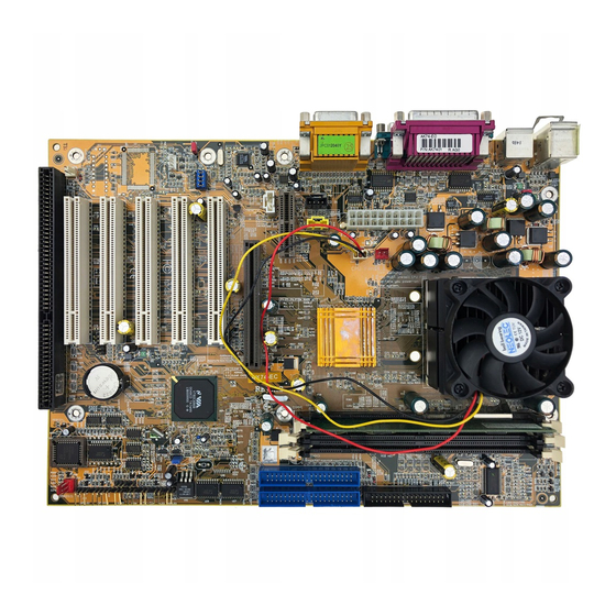
- Page 14 Hardware Installation Chapter 2 - Hardware Installation 2.1 System Board Layout AK74-SC (VIA KT133 - VT8363 and VT82C686A; supports onboard audio) ®...
- Page 15 Hardware Installation AK74-EC (VIA KT133 - VT8363 and VT82C686B; supports onboard audio) ®...
- Page 16 Hardware Installation AK74-EN (VIA KT133 - VT8363 and VT82C686B) ®...
- Page 17 Hardware Installation AK74-AC (VIA KT133 - VT8363A and VT82C686B; supports onboard audio) ® Note: The illustrations on the following pages are based on the AK74-SC/ EC/AC system boards, which are boards that support onboard audio.
- Page 18 Hardware Installation Warning: Electrostatic discharge (ESD) can damage your system board, processor, disk drives, add-in boards, and other components. Perform the upgrade instruction procedures described at an ESD workstation only. If such a station is not available, you can provide some ESD protection by wearing an antistatic wrist strap and attaching it to a metal part of the system chassis.
- Page 19 Hardware Installation 2.2.1 Installing the DIM Module...
- Page 20 Hardware Installation 2.3 Jumper Settings for Clearing CMOS Data Clear CMOS Data - Jumper JP8 a) CMOS data becomes corrupted. b) You forgot the supervisor or user password. c) You are unable to boot-up the computer system because the processor’s bus clock was incorrectly set in the BIOS.
- Page 21 Hardware Installation 2.4 Jumper Settings for the Onboard Audio Codec (AK74-SC/EC/AC) Onboard Audio Codec Settings - Jumpers JP4, JP5, JP6 and JP7...
- Page 22 Hardware Installation 2.5 Jumper Settings for Selecting the CPU’s Front Side Bus (AK74-AC) CPU Front Side Bus Select - Jumper JP10...
- Page 23 Hardware Installation 2.6 Jumper Settings for Selecting the USB Power USB Power Select for USB 1 and USB 2 - Jumper JP3...
- Page 24 Hardware Installation Ports and Connectors 2.7.1 Serial Ports 2.7.2 PS/2 Mouse and PS/2 Keyboard Ports Warning: Make sure to turn off your computer prior to connecting or disconnecting a mouse or keyboard. Failure to do so may damage the system board.
- Page 25 Hardware Installation 2.7.3 Parallel Port Setting Function 2.7.4 Floppy Disk Drive Connector...
- Page 26 Hardware Installation Connecting the Floppy Disk Drive Cable 2.7.5 IDE Disk Drive Connector Connecting the IDE Disk Drive Cable...
- Page 27 Hardware Installation Note: Refer to your disk drive user’s manual for information about selecting proper drive switch settings. Adding a Second IDE Disk Drive Important: If you encountered problems while using an ATAPI CD-ROM drive that is set in Master mode, please set the CD-ROM drive to Slave mode.
- Page 28 Hardware Installation 2.7.6 Universal Serial Bus Ports Pin Function Function...
- Page 29 Hardware Installation 2.7.7 IrDA Connector Function Note: The sequence of the pin functions on some IrDA cable may be reversed from the pin function defined on the system board. Make sure to connect the cable to the IrDA connector according to their pin functions.
- Page 30 Hardware Installation 2.7.8 CPU Fan Connector with CPU Fan Protection Function...
- Page 31 Hardware Installation Function...
- Page 32 Hardware Installation 2.7.9 Chassis Fan Connector Function...
- Page 33 Hardware Installation 2.7.10 Second Chassis Fan Connector Function 2.7.11 Game/MIDI Port (AK74-SC/EC/AC)
- Page 34 Hardware Installation 2.7.12 Audio Jacks (AK74-SC/EC/AC) Line-out Jack (J6 - Lime) Line-in Jack (J7 - Light Blue) Mic-in Jack (J8 - Pink)
- Page 35 Hardware Installation 2.7.13 Internal Audio Connectors (AK74-SC/EC/AC) AUX-in and CD-in Function Function...
- Page 36 Hardware Installation 2.7.14 Wake-On-LAN Connector Function Important: The 5VSB power source of your power supply must support a minimum of ≥ 720mA.
- Page 37 Hardware Installation 2.7.15 Wake-On-Ring Connector Function Important: If you are using a modem add-in card, the 5VSB power source of your power supply must support a minimum of ≥ 720mA.
- Page 38 Hardware Installation 2.7.16 AGP 4x LED and DIMM/PCI Standby Power LED AGP 4x LED DIMM Standby Power LED PCI Standby Power LED 3.3VSB Standby for PCI (Jumper JP1) Important: Lighted LEDs serve as a reminder that you must power-off the system then turn off the power supply’s switch or unplug the power cord prior to installing any DIM modules or add-in cards.
- Page 39 Hardware Installation 2.7.17 Power Connector Function Function Important: The system board requires a minimum of 300W electric current.
- Page 40 Hardware Installation 2.7.18 Front Panel LEDs and Switches HD-LED: Primary/Secondary IDE LED G-LED: Green LED ATX-SW: ATX Power Switch G-SW: Green Switch RESET: Reset Switch SPEAKER: Speaker Connector...
- Page 41 Hardware Installation PWR-LED: Power/Standby LED Note: If a system did not boot-up and the Power/Standby LED did not light after it was powered-on, it may indicate that the CPU or memor y module was not installed properly. Please make sure they are properly inserted into their corresponding socket. Pin Assignment HD-LED G-LED...
- Page 42 Award BIOS Setup Utility Chapter 3 - Award BIOS Setup Utility 3.1 The Basic Input/Output System CMOS Setup Utility - Copyright (C) 1984-2000 Award Software Standard CMOS Features Frequency/Voltage Control Advanced BIOS Features Load Fail-Safe Defaults Load Optimized Defaults Advanced Chipset Features Integrated Peripherals Set Supervisor Password Power Management Setup...
- Page 43 Award BIOS Setup Utility CMOS Setup Utility - Copyright (C) 1984-2000 Award Software Standard CMOS Features Item Help Date (mm:dd:yy) Wed, Jun 21 2000 Time (hh:mm:ss) 4 : 35 : 5 Menu Level IDE Primary Master Press Enter None Change the day, month, IDE Primary Slave Press Enter None year and century...
- Page 44 Award BIOS Setup Utility IDE Primary/Secondar y Master/Slave Capacity Access Mode Drive A and Drive B None 360K, 5.25 in. 1.2M, 5.25 in. 720K, 3.5 in. 1.44M, 3.5 in. 2.88M, 3.5 in. Video EGA/VGA CGA 40 CGA 80 Mono...
- Page 45 Award BIOS Setup Utility Halt On No Errors All Errors All, But Keyboard All, But Diskette All, But Disk/Key Base Memory Extended Memory T otal Memory...
- Page 46 Award BIOS Setup Utility 3.1.2 Advanced BIOS Features CMOS Setup Utility - Copyright (C) 1984-2000 Award Software Advanced BIOS Features Item Help Disabled Virus Warning Enabled CPU L1 Cache Menu Level Enabled CPU L2 Cache Enabled CPU L2 Cache ECC Checking Allows you to choose Enabled Quick Power On Self Test...
- Page 47 Award BIOS Setup Utility CPU L1 Cache and CPU L2 Cache CPU L2 Cache ECC Checking Quick Power On Self Test First Boot Device, Second Boot Device, Third Boot Device and Boot Other Device Swap Floppy Drive Boot Up Floppy Seek...
- Page 48 Award BIOS Setup Utility Boot Up NumLock Status Typematic Rate Setting Disabled Enabled Typematic Rate (Chars/Sec) Typematic Delay (Msec) Security Option System Setup...
- Page 49 Award BIOS Setup Utility OS Select for DRAM > 64MB HDD S.M.A.R.T. Capability...
- Page 50 Award BIOS Setup Utility 3.1.3 Advanced Chipset Features CMOS Setup Utility - Copyright (C) 1984-2000 Award Software Advanced Chipset Features Item Help Disabled DRAM Timing By SPD SDRAM Cycle Length Menu Level 100MHz DRAM Clock Disabled System BIOS Cacheable Disabled Video RAM Cacheable AGP Aperture Size Enabled...
- Page 51 Award BIOS Setup Utility SDRAM Cycle Length DRAM Clock System BIOS Cacheable Video RAM Cacheable AGP Aperture Size AGP-4X Mode AGP Driving Control AGP Driving Value...
- Page 52 Award BIOS Setup Utility OnChip USB USB Keyboard Support OnChip Sound (AK74-SC/EC/AC) OnChip Modem...
- Page 53 Award BIOS Setup Utility 3.1.4 Integrated Peripherals CMOS Setup Utility - Copyright (C) 1984-2000 Award Software Integrated Peripherals Item Help On-Chip Primary IDE Enabled On-Chip Secondary IDE Enabled Menu Level IDE Prefetch Mode Enabled IDE Primary Master PIO Auto IDE Primary Slave PIO Auto IDE Secondary Master PIO Auto...
- Page 54 Award BIOS Setup Utility Auto Mode 0-4 IDE Primary Master/Slave UDMA and IDE Secondary Master/ Slave UDMA Auto Disabled Init Display First PCI Slot IDE HDD Block Mode Enabled Disabled Onboard FDD Controller Enabled Disabled...
- Page 55 Award BIOS Setup Utility Onboard Serial Port 1 and Onboard Serial Port 2 Auto 3F8/IRQ4, 2F8/IRQ3, 3E8/IRQ4, 2E8/IRQ3 Disabled UART2 Mode Select IR Function Duplex Half Full TX,RX Inverting Enable Onboard Parallel Port 378/IRQ7, 3BC/IRQ7, 278/IRQ5 Disabled...
- Page 56 Award BIOS Setup Utility Parallel Port Mode Normal “ECP (Extended Capabilities Port)” “EPP (Enhanced Parallel Port)” ECP Mode Use DMA EPP Mode Select Onboard Legacy Audio (AK74-SC/EC/AC) Sound Blaster SB I/O Base Address SB IRQ Select...
- Page 57 Award BIOS Setup Utility SB DMA Select MPU-401 MPU-401 I/O Address Game Port (200-207H)
- Page 58 Award BIOS Setup Utility 3.1.5 Power Management Setup CMOS Setup Utility - Copyright (C) 1984-2000 Award Software Power Management Setup Item Help ACPI Function Enabled Power Management Press Enter Menu Level ACPI Suspend Type S1(POS) PM Control by APM Video Off Option Suspend ->...
- Page 59 Award BIOS Setup Utility Min Saving Max Saving User Define HDD Power Down Doze Mode Suspend Mode ACPI Suspend Type S1(POS) S3(STR) PM Control by APM...
- Page 60 Award BIOS Setup Utility Video Off Option Always On Suspend -> Off All Modes -> Off Video Off Method V/H SYNC + Blank Blank Screen DPMS Support MODEM Use IRQ Soft-Off by PWRBTN Delay 4 Sec Instant-Off...
- Page 61 Award BIOS Setup Utility PWR Lost Resume State Keep Off Turn On Last State Wake Up Events USB Resume from S3 LPT & COM HDD & FDD PCI Master...
- Page 62 Award BIOS Setup Utility Resume On LAN/Ring • • Resume By Alarm Enabled Disabled Date (of Month) 1-31 Resume Time (hh:mm:ss) Primary INTR...
- Page 63 Award BIOS Setup Utility IRQs Activity Monitoring 3.1.6 PnP/PCI Configurations CMOS Setup Utility - Copyright (C) 1984-2000 Award Software PnP/PCI Configurations Item Help Reset Configuration Data Disabled Menu Level Resources Controlled By Auto(ESCD) IRQ Resources Press Enter Default is Disabled. Select Enabled to PCI/VGA Palette Snoop Disabled...
- Page 64 Award BIOS Setup Utility Resources Controlled By Auto(ESCD) Manual IRQ Resources PCI/VGA Palette Snoop Enabled Disabled Assign IRQ for VGA Note: When Disabled, a “Yellow” mark will appear in Windows 95’s Device Manager.
- Page 65 Award BIOS Setup Utility Assign IRQ for USB Note: When Disabled, a “Yellow” mark will appear in Windows 95’s Device Manager.
- Page 66 Award BIOS Setup Utility 3.1.7 PC Health Status CMOS Setup Utility - Copyright (C) 1984-2000 Award Software PC Health Status Item Help Current System Temp. 27C/80F Current CPU Temperature 37C/98F Menu Level Current CPU Fan Speed 0 RPM Current Chassis Fan Speed 0 RPM Vcore 1.75 V...
- Page 67 Award BIOS Setup Utility CPU Fan Protection CPU Temp. Prot. Function and CPU Temp. Prot. Alarm CPU Temperature References...
- Page 68 Award BIOS Setup Utility 3.1.8 Frequency/Voltage Control CMOS Setup Utility - Copyright (C) 1984-2000 Award Software Frequency/Voltage Control Item Help CPU Vcore Select Default Spread Spectrum Modulated Disabled Menu Level CPU Host/PCI Clock Default ↑↓→← Move Enter:Select +/-/PU/PD:Value F10:Save ESC:Exit F1:General Help F5:Previous Values F6:Fail-Safe Defaults...
- Page 69 Award BIOS Setup Utility CPU Host/PCI Clock Important: Overclocking may result to the processor’s or system’s instability and are not guaranteed to provide better system performance. Note: Use a PS/2 or AT (requires a DIN to mini DIN adapter) keyboard for method 2.
- Page 70 Award BIOS Setup Utility 3.1.9 Load Fail-Safe Defaults 3.1.10 Load Optimized Defaults...
- Page 71 Award BIOS Setup Utility 3.1.11 Set Supervisor Password 3.1.12 Set User Password...
- Page 72 Award BIOS Setup Utility 3.1.13 Save & Exit Setup 3.1.14 Exit Without Saving 3.2 Updating the BIOS...
- Page 73 " Supported Softwares Chapter 4 - Supported Softwares 4.1 Desktop Management Interface (DMI) 4.1.1 Running the DMI Utility...
- Page 74 " Supported Softwares 4.1.2 Using the DMI Utility Award DMI Configuration Utility Copyright Award Software Inc, 1996 [Edit DMI] [Add DMI] [Load DMI File] [Save DMI File] BIOS *** BIOS Auto Detect *** System Enclosure/Chassis Type : BIOS Information Processor Handle : 0000 Memory Controller Vendor Name :...
- Page 75 " Supported Softwares Add DMI ← → ↑ ↓ Load DMI File ← → Press [Enter] to select DMI file for load Do you want to execute? (Y/N) Save DMI File ← → Press [Enter] to select DMI file for save...
- Page 76 " Supported Softwares 4.2 VIA Hardware Monitor Note: Use this utility only in Windows 95, Windows 98, Windows ® ® ® 98 SE, Windows ME, Windows 2000 or Windows NT ® ® ® operating system. 4.3 VIA Service Pack ® Service Pack Installation Notes ®...
- Page 77 CD, installing the bundled VxD driver may cause problems. If you are using this type of card, we recommend that you install first the AGP card’s VGA driver before installing the VIA Service Pack. 4.4 Audio Drivers and Software Application (AK74-SC/EC/AC) ...
- Page 78 " Supported Softwares 4.5 Drivers and Utilities Installation Notes ...
- Page 79 Using the Suspend to RAM Function Appendix A - Using the Suspend to RAM Function A.1 Using the Suspend to RAM Function CMOS Setup Utility - Copyright (C) 1984-2000 Award Software Power Management Setup Item Help ACPI Function Enabled Power Management Press Enter Menu Level ACPI Suspend Type...
- Page 80 Using the Suspend to RAM Function ® ®...
- Page 81 Using the Suspend to RAM Function...
- Page 82 Using the Suspend to RAM Function ®...
- Page 83 System Error Message Appendix B - System Error Message B.1 POST Beep B.2 Error Messages CMOS BATTERY HAS FAILED Caution: Danger of explosion if battery incorrectly replaced. Replace only with the same or equivalent type recommended by the manufacturer. Dispose of used batteries according to the battery manufacturer’s instructions.
- Page 84 System Error Message FLOPPY DISK(S) fail (80) FLOPPY DISK(S) fail (40) Hard Disk(s) fail (80) Hard Disk(s) fail (40) Hard Disk(s) fail (20) Hard Disk(s) fail (10) Hard Disk(s) fail (08) Keyboard is locked out - Unlock the key Keyboard error or no keyboard present Manufacturing POST loop BIOS ROM checksum error - System halted Memory test fail...
- Page 85 Troubleshooting Appendix C - Troubleshooting C.1 Troubleshooting Checklist CPU Fan Protection After booting up the system, a beeping alarm sounded then the system’s power was turned off:...
- Page 86 Troubleshooting Monitor/Display If the display screen remains dark after the system is turned on: The picture seems to be constantly moving. The screen seems to be constantly wavering. Power Supply When the computer is turned on, nothing happens.
- Page 87 Troubleshooting Floppy Drive The computer cannot access the floppy drive. Hard Drive Hard disk failure. Excessively long formatting period. Parallel Port The parallel printer doesn’t respond when you try to print.
- Page 88 Troubleshooting Serial Port The serial device (modem, printer) doesn’t output anything or is outputting garbled characters. Keyboard Nothing happens when a key on the keyboard was pressed. System Board...
Need help?
Do you have a question about the AK74-SC and is the answer not in the manual?
Questions and answers