Advertisement
Quick Links
SPECIFICATIONS:
Model ........................................ 40M2C
Frequency Range ...................... 7.0-7.3 MHz 3 Seg
Gain ........................................... 11 dBi @ 70' / 6.1 FS
Front to back .............................. 25 dB @ 70 ft / 15 FS
Beamwidth ............................... E=74°
Feed type ................................... Hair pin match
Feed Impedance. ....................... 50 Ohms Unbalanced
Maximum VSWR ....................... See Curve
Input Connector ......................... SO-239, Other avl.
FEATURES:
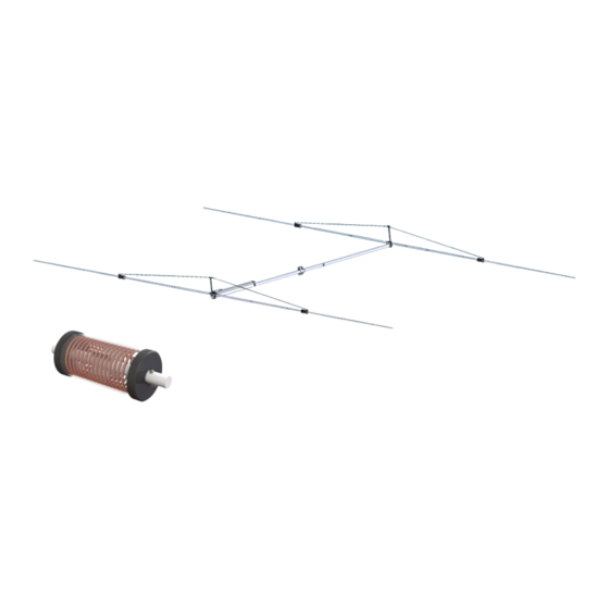
The 40M2C is the latest addition to our already exceptional 40 meter Yagi lineup. Using all the latest design and manufacturing tools,
including 3D printed coil forms. Our coil loaded antennas now make it difficult to choose a full size equivalent. Mounting this Yagi at 70
feet creates incredibly clean pattern with unique front to rear and above performance.
Our new covered coil design features 3/16" diameter copper clad soft drawn aluminum that has great power handling and high efficien-
cy (Q over 900) combined with low weight. We use 3D printing for precision coil forms. The coils are located at the optimum place in
each element half. The location of the coil is important for best performance and this careful placement also breaks the element into
small electrical lengths that appear shorter than 20 meter elements. This means there is little or no interaction with any 20 meter Yagi
on the same mast OR on the same boom. Our new DUAL BAND "CYCLE BUSTER " takes full advantage of this unique feature.
Mechanically, the coil loading offers a cleaner look with less wind area and fewer connections. Wind and ice loading are reduced as
well. We continue to offer the same unbreakable element mounting and OVER HEAD element support. The rugged, time tested ele-
ments and 3 kW 1:1 Balun are part of the package. All Hardware is stainless steel except for the Galvanized U-bolts and saddles.
(Stainless U-bolts tend to Gall and freeze up) and used in our other 40M Yagis.
M2 Antenna Systems, Inc. 4402 N. Selland Ave. Fresno, CA 93722
M2 Antenna Systems, Inc.
Model No: 40M2C
*Subtract 2.14 from dBi for dBd
Tel: (559) 432-8873 Fax: (559) 432-3059 Web: www.m2inc.com
©2021 M2 Antenna Systems Incorporated
Power Handling .......................... 3 Kw PEP, Higher avl.
Boom Length / Dia ..................... 19.5' / 3.0 x .065 Wall
Element Length / Dia. ................ 50 Ft. / 1-1/2" To 1/2"
Turning Radius: .......................... 27 Ft.
Stacking Distance ...................... 70 Ft.
Mast Size ................................... 2" to 3 " Nom.
Wind area / Survival ................... 4.85 Sq. Ft. / 100 MPH
Weight / Ship Wt. ....................... 76 Lbs. / Lbs.
05/017/21
Rev.01
Advertisement

Related Manuals for M2 Antenna Systems 40M2C


Summary of Contents for M2 Antenna Systems 40M2C
- Page 1 FEATURES: The 40M2C is the latest addition to our already exceptional 40 meter Yagi lineup. Using all the latest design and manufacturing tools, including 3D printed coil forms. Our coil loaded antennas now make it difficult to choose a full size equivalent. Mounting this Yagi at 70 feet creates incredibly clean pattern with unique front to rear and above performance.
- Page 2 40M2C ANTENNA OVERVIEW BEFORE YOU BEGIN: Look over all the DRAWINGS to get familiar with the various parts and assem- blies in the system. Tools handy for assembly process: screwdriver, 11/32”, 7/16”, 1/2”, 9/16” and 5/8” spin-tites, end wrenches and/or sockets, and a measuring tape.
- Page 3 40M ELEMENT HALF OVERVIEW ELEMENT SECTION ELEMENT SECTION #1 (M2AEP40MC-1) (M2AEP40MC-3) ELEMENT TIP ELEMENT ELEMENT (SAEL40M2C) OVERHAED SUPPORT LENGTH VARIES (M2APL0212) DEPENDING ON ELEMENT ELEMENT SECTION #4 (M2AEP40MC-4) ELEMENT SECTION #6 BOLT, (M2AEP40MC-6) 1/4-20 X 2” ELEMENT SECTION #5 & LOCK NUT (M2AEP40MC-5) COIL ASSEMBLY 2 (QTY) SCREW,...
- Page 4 40M COIL OVERVIEW BOOM ELEMENT TIP ELEMENT SECTION #4 40M COIL COIL INSULATOR ELEMENT SECTION #6 (M2AEP40MC-4) (M2ACA1550) (M2AFG0050) (M2AEP40MC-6) COIL POST COIL END CAP COIL SUPPORT (M2ACA1551) (M2ACA1552) (M2ACA1554) (QTY 2) (QTY 2) NOTE: COVER REMOVED FOR ILLUSTRATION PURPOSES.
- Page 5 40M COIL ASSEMBLY INSTRUCTIONS STEP 1: The coil comes wound tight with 16 total turns from the factory, When final assembled, you will end with 15.5 total turns. The excess material will be trimmed off after the coil is in its final position. Using a permanent marker, draw a straight line from one end of the coil to the other.
- Page 6 40M COIL ASSEMBLY INSTRUCTIONS COIL POST ELEMENT SEC- STEP 7: (M2ACA1551) TION #4 The second COIL POST is mounted on the OP- SCREW, 8-32 X 1-1/4” POSITE SIDE of the COIL INSULATOR so 15 1/2 turns of SET SCREW, 1/4-20 X 1/4” the COIL are used.
- Page 7 40M2C BOOM ASSEMBLY INSTRUCTIONS STEP 11: SCREW, 1/4-20 X 3-1/2” At this point it will be helpful to perform the remaining LOCKNUT, 1/4-20 assembly steps with the BOOM ASSEMBLY elevated off the ground (about 3 feet). This can be accomplished by using sawhorses or something similar.
- Page 8 40M2C ELEMENT MOUNT ASSEMBLY INSTRUCTIONS ELEMENT MOUNT ASSEMBLY REFECTOR OR DIRECTOR VERTICAL RISER ASSEMBLY STEP 12: (SAVR0010) ELEMENT CENTER SPLICE Assemble the ELEMENT MOUNT (M2ASR0050) assemblies for the reflector and front director element. Refer to the assembly drawing to aid in BOLT, 1/4-20 X 3-1/2”...
- Page 9 40M2C ELEMENT FINAL ASSEMBLY INSTRUCTIONS USE 3/16 THIMBLE AND TIE KNOTS USE LOCK BLOCK ROPE SEE DIAGRAM ROUTING DETAIL SEE DIAGRAM ELEMENT SECTION #3 ELEMENT TIP COIL ASSEMBLY (M2AEP40MC-3) (SAEL40MCDD) LENGTH VARIES DEPENDING ELEMENT SECTION #1 ELEMENT SECTION #2 ELEMENT SECTION #5...
- Page 10 40M2C ASSEMBLY DETAIL ELEMENT ASSEMBLY REFLECTOR OR DIRECTOR ELEMENT USE 3/16 THIMBLE AND TIE KNOTS AND TAPE VERTICAL RISER SEE DIAGRAM ASSEMBLY (SAVR0010) BOLT, 1/4-20 X 2-1/2” BOLT, 1/4-20 X 3-1/2” LOCKNUT, 1/4-20 (QTY 4) AND LOCKNUT (QTY 2) BOLT, 1/4-20 X 2”...
- Page 11 40M2C HAIR PIN AND BALUN ASSEMBLY INSTRUCTIONS STEP 21: Refer to the dimension sheet for element placement. With the boom elevated on sawhorses or equivalent, using a long tape measure and a permanent marker lay the boom out by marking the centers of each element. Equalize the amount of extra boom at both ends on the antenna.
- Page 12 GENERIC COMPRESSION CLAMP DETAIL...
- Page 13 LOCK BLOCK AND KNOT DETAIL LOCK BLOCK ROPE ROUT DETAIL After final adjustments of knots and lock blocks, use electrical tape to tape the excess rope down to the main rope as prevention for rope slippage.
- Page 14 M2 40M2C DIMENSION SHEET TUNING CHART EXSPOSED ELEMENT TIP 7.00 TO 7.100 MHZ 7.100 TO 7.230 MHZ 7.160 TO 7.300 MHZ REFLECTOR TIP 52.00” 46.50” 44.50” DRIVEN ELEMENT TIP 41.50” 36.25” 33.50” HAIR PIN POSITION 54.00” 54.00” 54.00” 231.00” 54.00””...
- Page 15 40M2C PARTS & HARDWARE DESCRIPTION BOOM SECTION #1, 3.0” X .065” X 95”, SOE (M2ABS40M2-1) ................... 1 BOOM SECTION #2, 3.0” X .065” X 95” SOE (M2ABS40M2-2) ................... 1 BOOM SECTION #3, 3.0” X .065” X 55” (M2ABS40M2-3) ....................1 ELEMENT SECTION #1: 1-1/2”...
Need help?
Do you have a question about the 40M2C and is the answer not in the manual?
Questions and answers