Advertisement
SPECIFICATIONS:
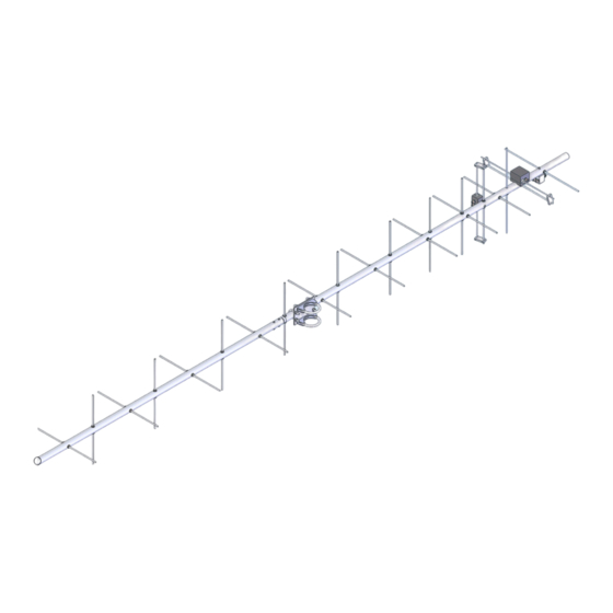
Model ........................................ 403CP20
Frequency Range ...................... 398 To 408 MHz
*Gain .......................................... 14 dBic
Front to back .............................. 16 dB Typical
Elipticity ...................................... <3dB
Feed type ................................... "T" Match
Feed Impedance. ....................... 50 Ohms Unbalanced
Maximum VSWR ........................ 1.5:1 Typical
Input Connector ......................... "N" Female
FEATURES:
The 403CP20 is a light, medium performance circularly polarized antenna. Optimum match and gain are
between 398 & 408 MHz for the satellite band. Computer design techniques help keep spurious side lobes low down
for optimum signal to noise ratios. This antenna features the same CNC machined, O-ring and silicone-gel sealed,
driven element assemblies common to all M
regardless of weather.
M2 Antenna Systems, Inc. 4402 N. Selland Ave. Fresno, CA 93722
M2 Antenna Systems, Inc.
Model No: 403CP20
*Subtract 2.14 from dBi for dBd
2
Yagi antennas. This insures years of trouble free performance
Tel: (559) 432-8873 Fax: (559) 432-3059 Web: www.m2inc.com
©2022 M2 Antenna Systems Incorporated
Power Handling .......................... 1.5 kW (250W PS-I)
Boom Length / Dia ..................... 77" / 1"
Maximum Element Length ......... 15"
Turning Radius: .......................... Call
Stacking Distance ...................... Call
Mast Size ................................... 1-1/2" to 2" Nom.
Wind area / Survival ................... 0.08 Sq. Ft. / 100MPH
Weight / Ship Wt. ....................... 6 Lbs. / 8 Lbs.
08/17/22
Rev.00
Advertisement
Table of Contents

Related Manuals for M2 Antenna Systems 403CP20


Summary of Contents for M2 Antenna Systems 403CP20
- Page 1 *Subtract 2.14 from dBi for dBd FEATURES: The 403CP20 is a light, medium performance circularly polarized antenna. Optimum match and gain are between 398 & 408 MHz for the satellite band. Computer design techniques help keep spurious side lobes low down for optimum signal to noise ratios.
- Page 2 403CP20 ASSEMBLY MANUAL TOOL REQUIRED FOR ASSEMBLY: screwdriver, 11/32 nut driver or wrench, 7/16” and1/2” socket or end wrenches, measuring tape. 1. Assemble the boom using 8-32 X 1-1/4 screws and locknuts to join sections. Sections may may be swaged to each other or use 7/8”...
- Page 3 403CP20 DIMENSION SHEET...
- Page 4 INSTALLATION TIPS 13. The 403CP20 is a circular polarized antenna and creates a field in all planes or polarities. Performance DETERIORATES SIGNIFICANTLY if it is mounted on a metal (conductive) mast or crossboom. A mast or crossboom of any NON- CONDUCTIVE material must be used.
- Page 5 403CP20 PARTS & HARDWARE DESCRIPTION Boom section #1, 1 x .058 x 59" SOE ......1 Boom section #2, 1 x .058 x 19.5" ....... 1 Boom to mast plate, 3 x 4 x .125" ........ 1 Elements, 3/16" alum. rod x (see dims.) ..... 20 Driven element block assembly, ........
- Page 6 Installation is easy and involves only the removal of one of the original Driven Element assemblies and then mounting the PS -400CM in its place. M2 Antenna Systems, Inc. 4402 N. Selland Ave. Fresno, CA 93722 Tel: (559) 432-8873 Fax: (559) 432-3059 Web: www.m2inc.com 04/12/14 ©2014 M2 Antenna Systems Incorporated...
Need help?
Do you have a question about the 403CP20 and is the answer not in the manual?
Questions and answers