Advertisement
SPECIFICATIONS:
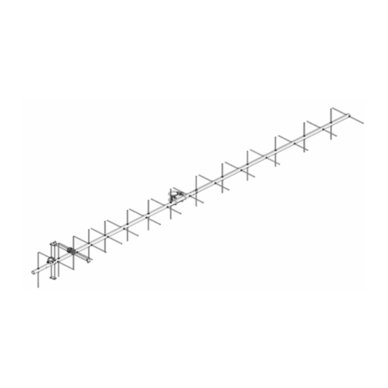
Model ................................. 418CP30
Frequency Ranges* ........... 414-427/435-438 MHz
Gain** .................................. 16.0 dBi
Front to back ....................... 21 dB Typical
Ellipticity .............................. 1.5 dB Typical
Beamwidth ........................ 35
Feed Impedance. ................ 50 , Unbalanced
Maximum VSWR ................. 1.7:1 Max
Input Connector .................. "N" Female
FEATURES:
The 418CP30 is a practical sized, yet high performance circular polarized antenna with a remarkably
clean pattern. The versatile pattern is important in order to match the antenna's noise temperature with modern
low noise preamps. This antenna is ideal for commercial LEO satellite work and was designed with a second res-
onance band at amateur frequencies of 335-338 MHz, with a peak gain of 16 dBi. The CNC machined driven
element module is O-ring sealed and weather tight for low maintenance and long-term peak performance. Inter-
nal connected are encapsulated in a space-age silicone gel that seals out moisture and improves power han-
dling. The 3/16" 6061-T6 rod elements are centered to minimize interaction and maintain good ellipticity. Insula-
tors are UV stabilized and locked in place with stainless keepers. Rugged construction, uncompromising perfor-
mance for the boom length: that's the M
M2 Antenna Systems, Inc. 4402 N. Selland Ave. Fresno, CA 93722
Tel: (559) 432-8873 Fax: (559) 432-3059 Web: www.m2inc.com
M2 Antenna Systems, Inc.
Model No: 418CP30
o
circular
*Dual Band Resonance
2
418CP30!
©2018 M2 Antenna Systems Incorporated
Power Handling ..........................600W
Boom Length / Dia ......................128.5" / 1" Dia
Longest Element.........................13.75", 3/16" Rod
Stacking Distance .......................50"
Mast Size ....................................1-1/2"/ 2"
Wind area / Survival .....................1 ft.
Weight / Ship Wt. ........................5 lbs. / 7 lbs. UPS
**Subtract 2.14 from dBi for dBd
2
/ 120 mph
5/14/19
REV B
Advertisement
Table of Contents

Related Manuals for M2 Antenna Systems 418CP30


Summary of Contents for M2 Antenna Systems 418CP30
-
Page 1: Specifications
**Subtract 2.14 from dBi for dBd FEATURES: The 418CP30 is a practical sized, yet high performance circular polarized antenna with a remarkably clean pattern. The versatile pattern is important in order to match the antenna’s noise temperature with modern low noise preamps. This antenna is ideal for commercial LEO satellite work and was designed with a second res- onance band at amateur frequencies of 335-338 MHz, with a peak gain of 16 dBi. - Page 2 418CP30 ASSEMBLY MANUAL TYPICAL TOOLS REQUIRED: measuring tape, phillips screwdriver, 5/16”, 11/32”, 7/16”, and 1/2 spin-tite, end wrenches and / or sockets. Heavy duty models may require larger sizes. 1. Lay out the boom sections and assemble using the DIMENSION sheet as a guide for position and hardware.
- Page 3 418CP30 ASSEMBLY MANUAL 7. Generally the balun is installed in one long loop. Attach balun to the block connectors and tighten gently using a 7/16" end wrench. Form the balun coax close to the boom and secure with cable ties (snug but not crushing or kinking the coax).
- Page 4 418CP30 DIMENSION SHEET NOTE: RIGHT HAND CIRCULARITY SHOWN...
- Page 5 418CP30 DRIVEN ELEMENT CABLE ROUTES PHASING LINE D.E. BLOCK 1/4 WAVE SCREW, 8-32 X 1-1/4” JUNCTION BLOCK D.E. BALUN SCREW, 8-32 X 1-1/4” D.E. BLOCK SCREW, 8-32 X 1-1/4” D.E. BALUN PHASING LINE 3/4 WAVE FIG. 4 CABLE ROUTING DIAGRAM...
- Page 6 418CP30 PARTS & HARDWARE DESCRIPTION ..............…………………………..QTY BOOM SECTION #1, 1” X .058” X 48" SOE (M2ASB418CP30-1) ......1 BOOM SECTION #2, 1” X .058” X 60” SOE (M2ASB418CP30-2) ......1 BOOM SECTION #3, 1” X .058” X 26.5” (M2ASB418CP30-3) ........ 1 BOOM-TO-MAST PLATE, 3”...
Need help?
Do you have a question about the 418CP30 and is the answer not in the manual?
Questions and answers