Table of Contents
Advertisement
Operator's Manual
13" 24V MAX* Lithium-Ion Cordless Mower CLM2413A
Save this manual for future reference
* Maximum initial battery workload voltage (measured without a workload) is 24 volts.
Nominal voltage is 21.6 volts.
Battery Model Number is 24LB4005-C
Charger Model Number is 24LFC14-ETL
Read all safety rules and instructions carefully before operating this tool.
Distributed By: Suzhou Cleva Electric Appliance Co., Ltd.
NO.8 Ting Rong Street 215122 Suzhou - China
Advertisement
Table of Contents

Subscribe to Our Youtube Channel
Related Manuals for LawnMaster CLM2413A


Summary of Contents for LawnMaster CLM2413A
- Page 1 Operator's Manual 13" 24V MAX* Lithium-Ion Cordless Mower CLM2413A Save this manual for future reference * Maximum initial battery workload voltage (measured without a workload) is 24 volts. Nominal voltage is 21.6 volts. Battery Model Number is 24LB4005-C Charger Model Number is 24LFC14-ETL Read all safety rules and instructions carefully before operating this tool.
-
Page 2: Table Of Contents
TABLE OF CONTENTS SPECIFICATIONS IMPORTANT SAFETY INSTRUCTIONS SYMBOLS 9-11 KNOW YOUR LAWN MOWER 12-13 ASSEMBLY 14-20 BATTERY PACK AND CHARGER 21-23 OPERATION 24-26 MAINTENANCE 27-31 ENVIRONMENTALLY SAFE BATTERY DISPOSAL TROUBLESHOOTING 33-34 ® LAWNMASTER WARRANTY EXPLODED VIEW PARTS LIST NOTES 38-39... -
Page 3: Specifications
SPECIFICATIONS 24V MAX* CORDLESS MOWER Type Cordless, Battery-powered No-load Speed 3700 RPM Deck Width 13.15" (334 mm) Cutting Width 12.44" (316 mm) Height Adjustments 5 Positions (1"-2.55") (25-65 mm) Wheel Size 5.51 " (140 mm) / 5.51 " (140 mm) Unit Weight (With 4.0Ah Battery) 23.15 lbs (10.5 kg) BATTERY PACK... -
Page 4: Important Safety Instructions
IMPORTANT SAFETY INSTRUCTIONS INTRODUCTION This product has many features for making its use more pleasant and enjoyable. Safety, performance, and dependability have been given top priority in the design of this product making it easy to maintain and operate. WARNING This symbol indicates important safety instructions. - Page 5 IMPORTANT SAFETY INSTRUCTIONS all safety instructions could result in serious injury or death. ■ Do not operate the equipment while under the influence of alcohol or drugs. ■ Use lawn mower for the correct purpose. Do not use lawn mower for any job except that for which it is intended.
- Page 6 IMPORTANT SAFETY INSTRUCTIONS ■ Never attempt to make a wheel height adjustment while the motor is running. MAINTENANCE AND STORAGE ■ Use caution when servicing blades. Wrap the blade(s) or wear gloves. Replace damaged blades. Do not repair or alter blade(s). ■...
- Page 7 IMPORTANT SAFETY INSTRUCTIONS ■ Do not place battery powered lawn mowers or their batteries near fire or heat. This will reduce the risk of explosion and possibly injury. ■ Do not open or mutilate the battery. Released electrolyte is corrosive and may cause damage to the eyes or skin.
- Page 8 IMPORTANT SAFETY INSTRUCTIONS FCC COMPLIANCE ■ This device complies with Part 15 of the FCC Rules. Operation is subject to the following two conditions: - This device may not cause harmful interference, and - This device must accept any interference received, including interference that may cause undesired operation.
-
Page 9: Symbols
SYMBOLS Some of the following symbols may be used on this product. Please study them and learn their meaning. Proper interpretation of these symbols will allow you to operate the product better and safer. SYMBOL NAME DESIGNATION/EXPLANATION Volts Voltage Direct Current Type or a characteristic of current Amperes Current... - Page 10 SYMBOLS SYMBOL NAME DESIGNATION/EXPLANATION Keep hands and feet Danger: Keep hands and feet away. away Cutting Width Cutting diameter. Lithium-Ion Battery Designates that this tool is in compliance with lithium- Recycling ion battery recycling program requirements. Do not dispose of battery packs in rivers or immerse Keep Away From Water in water.
- Page 11 SYMBOLS The following signal words and meanings are intended to explain the levels of risk associated with this product. SYMBOL SIGNAL MEANING Indicates an imminently hazardous situation, which, if not DANGER avoided, will result in death or serious injury. Indicates a potentially hazardous situation, which, if not WARNING avoided, could result in death or serious injury.
-
Page 12: Know Your Lawn Mower
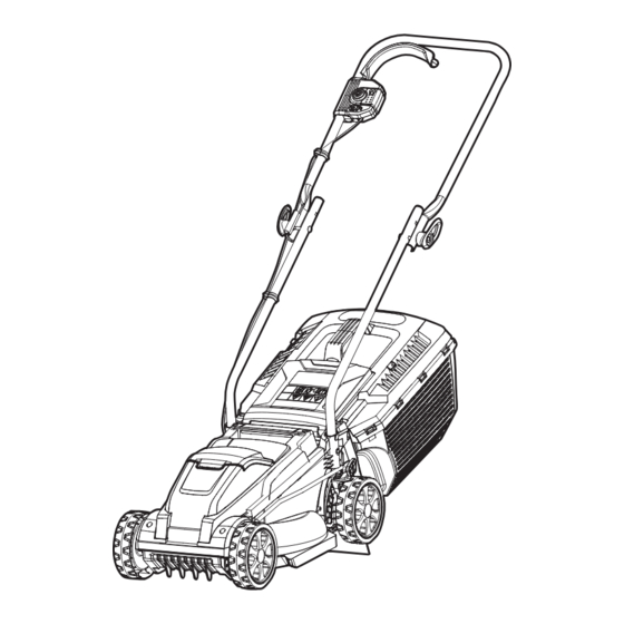
KNOW YOUR LAWN MOWER... - Page 13 KNOW YOUR LAWN MOWER Components 8.Wheel (×4) 16.Start/Stop Bale Switch 9.Deck 17.Battery Pack (×2) 1.Upper Handle 10.Battery Compartment Cover 18.Battery Release Button 2.Locking Knob 11.Safety Key (Inside the Battery 19.Battery Charger 3.Lower Handle Pack Compartment) 4.Grass Collection Bag 12.Carry Handle Handle 13.Grass Collection Bag Full 5.Rear Safety Flap...
-
Page 14: Assembly
ASSEMBLY UNPACKING This product requires assembly. ■ Carefully remove the product and any accessories from the box. Make sure that all items listed in the packing list are included. ■ Inspect the product carefully to make sure no breakage or damage occurred during shipping. ■... - Page 15 ASSEMBLY WARNING If any parts are damaged or missing do not operate this product until the parts are replaced. Failure to heed this warning could result in serious personal injury. Do not attempt to modify this product or create accessories not recommended for use with this product.
- Page 16 ASSEMBLY ASSEMBLING THE UPPER HANDLE 1. Fix the upper handle using the bolts, cable guide (pre-installed on cable) and the locking knobs, and turn the locking knob clockwise till it tightens (Fig. 2). There are two possible positions. NOTE: Make sure the cable guide is installed correctly on one side of the upper handle as shown to avoid cable damage when the upper handle is folded up and down.
- Page 17 ASSEMBLY 3. Align the cover and base of the grass collection bag at the front. Clip the two halves together, starting at the front and then moving to the sides (Fig. 5). Fig. 5 4.Slide the tongue into the front section of the grass collection bag and ensure it is securely placed (Fig. 6). 5.The completely assembled grass collection bag is as shown as below (Fig.
- Page 18 ASSEMBLY INSTALLING AND REMOVING THE GRASS COLLECTION BAG NOTE: The safety flap is spring operated. Ensure you have a firm grip when opening and closing to avoid personal injury. Installing the grass collection bag: 1. Lift the rear safety flap and hold it in position (Fig. 8). 2.
- Page 19 ASSEMBLY ADJUSTING THE CUTTING HEIGHT WARNING Do not at any time make any adjustment to the lawn mower without first stopping the motor and removing the safety key. Keep your feet away from the mower deck when adjusting its height. When shipped, the rear wheels on the mower are set to a low-cutting position.
- Page 20 ASSEMBLY INSTALLING / REMOVING THE BATTERY PACK WARNING If any parts are broken or missing, do not attempt to attach the battery pack to the mower or operate the mower until the broken or missing parts are replaced. Failure to do so could result in serious injury. Do not connect the battery and/or the safety key before the product is completely assembled.
-
Page 21: Battery Pack And Charger
BATTERY PACK AND CHARGER BATTERY CHARGING ® 1. Use only with 24V LawnMaster battery chargers. The battery charger supplied is specifically designed for the lithium-Ion battery used in this garden appliance. 2. Check the power voltage! Battery chargers operate on 120 V. - Page 22 BATTERY PACK AND CHARGER b) If the temperature range is correct and flashing red LED light continues, then remove and reinstall the battery pack. If the LED status repeats a second time, try to charge another identical battery. If the battery charges normally, dispose of the defective battery pack (see Environmental Safe Battery Disposal section).
- Page 23 BATTERY PACK AND CHARGER WARNING If any part of the charger is missing or damaged, do not operate it! Replace the charger with a new one. Failure to heed this warning could result in possible serious injury. Check the voltage! The voltage must comply with the information on the rating label. 1.
-
Page 24: Operation
OPERATION WARNING Do not allow familiarity with this type of product to make you careless. Remember that being careless for a fraction of a second is sufficient to inflict serious injury. WARNING Always wear safety goggles or safety glasses with side shields when operating this product. Failure to do so could result in objects being thrown into your eyes, resulting in possible serious injury. - Page 25 OPERATION GRASS COLLECTION BAG FULL INDICATOR (FIG. 16) The collection bag is equipped with a capacity indicator flap that indicates the filling volume during the mowing process. 1. When the grass collection bag full indicator is opened (during operation), the collection bag has efficient volume left to collect grass.
- Page 26 OPERATION Fig. 17 MOWING ON A SLOPE (Fig. 18) 1. Slopes are a major factor related to slip and fall accidents that can result in severe injury. Mowing on slopes requires extra caution. If you feel uneasy on a slope, do not mow it. For your safety, do not attempt to mow slopes greater than 15 degrees.
-
Page 27: Maintenance
MAINTENANCE WARNING When servicing, use only identical replacement parts. Use of any other parts may create a hazard or cause product damage. WARNING Always wear safety goggles or safety glasses with side shields during power tool operation or when blowing dust. If operation is dusty, also wear a dust mask. GENERAL MAINTENANCE Avoid using solvents when cleaning plastic parts. - Page 28 REPLACING THE MOWER BLADE NOTE: Remove safety key and battery before performing any maintenance! ® NOTE: Only use identical replacement blades. LawnMaster mower blade replacement part # 211049125. 1. Stop the motor and allow the blade to come to a complete stop.
- Page 29 MAINTENANCE Blade Blade Nut Wooden Block Fig. 19 Fig. 20 SHARPENING THE BLADE For best mowing performance, the mower blade must be kept sharp. A dull blade does not cut grass evenly and overloads the motor. Under normal circumstances, sharpening the blade twice during the mowing season is usually sufficient.
- Page 30 MAINTENANCE Fig. 21 Fig. 22 STORING THE MOWER 1. Remove mower safety key and battery. 2. Turn mower on its side and clean grass clippings that have accumulated on the underside of the mower deck. 3. Wipe the mower clean with a dry cloth. 4.
- Page 31 MAINTENANCE CLEANING THE MOWER WARNING To reduce the risk of electric shock, do not expose the mower to water. WARNING Do not at any time make any maintenance to the lawn mower without first stopping the motor and removing the safety key and battery pack. The underside of mower deck should be cleaned after each use as grass clippings, leaves, dirt and other debris will accumulate causing rust and corrosion.
-
Page 32: Environmentally Safe Battery Disposal
ENVIRONMENTAL SAFE BATTERY DISPOSAL The following toxic and corrosive materials are in the batteries used in this battery pack: lithium-ion, a toxic material. WARNING All toxic materials must be disposed of in a specific manner to prevent contamination of the environment. -
Page 33: Troubleshooting
TROUBLESHOOTING Suspected malfunctions are often due to causes that the user can fix themselves. Therefore, check the product using this section. In most cases the problem can be solved quickly. WARNING Only perform the steps described within these instructions! All further inspection, maintenance and repair work must be performed by an authorized service center or a similarly qualified specialist if you cannot solve the problem yourself! PROBLEM POSSIBLE CAUSE... - Page 34 TROUBLESHOOTING The cutting blade is not Tighten the blade bolts. assembled securely. Sharpen and balance the blade Mower vibrates The blade is not balanced. following instructions in this manual (see excessively and makes a page 29). Or replace the blade. lot of noise.
-
Page 35: Lawnmaster ® Warranty
® LAWNMASTER WARRANTY... -
Page 36: Exploded View
EXPLODED VIEW... -
Page 37: Parts List
PARTS LIST Key Number Drawing Number Description Quantity Motor Cover Assy. 111198146 Safety Key PCB Assy. Key Holder Assy. Motor Drive Assy. 211068103 Wheel Assy. (5.51'') Washer Assy. Base Assy. Front Axle Assy. Ballast Assy. Locating Ring 211049125 Blade Bolt Assy. Height Connecting Rod Protective Plate Assy. -
Page 38: Notes
NOTES... - Page 39 NOTES...
Need help?
Do you have a question about the CLM2413A and is the answer not in the manual?
Questions and answers