
Related Manuals for Advantech TPC-650


Summary of Contents for Advantech TPC-650
- Page 1 TPC-650 Pentium-based panel PC with 5.7"/6.4" LCD flat panel display User's Manual...
-
Page 2: Copyright Notice
Copyright notice This document is copyrighted 2000 by Advantech Co., Ltd. All rights are reserved. Advantech Co., Ltd. reserves the right to make improve- ments to the products described in this manual at any time without notice. No part of this manual may be reproduced, copied, translated or transmitted in any form or by any means without the prior written permission of Advantech Co., Ltd. -
Page 3: Initial Inspection
We have carefully inspected the TPC-650 mechanically and electrically before shipment. It should be free of marks and scratches and in perfect working order upon receipt.As you unpack the TPC-650, check it for signs of shipping damage. (For example, damaged box, scratches, dents, etc.) If it is damaged or it fails to meet the specifica-... - Page 4 FCC Class A notes This equipment has been tested with a Class A computing device and has been found to comply with Part 15 of FCC Rules. Operation in a residential area may cause unacceptable interference to radio and TV receptions, requiring the operator to take whatever steps are necessary to correct the interference.
-
Page 5: Safety Instructions
The sound pressure level at the operator's position according to IEC 704-1:1982 is equal to or less than 70 dB(A). DISCLAIMER: This set of instructions is given according to IEC 704-1. Advantech disclaims all responsibility for the accuracy of any statements contained herein. - Page 6 60° C (140° F), weil diesen Temperaturen das Gerät zerstören könten. Der arbeitsplatzbezogene Schalldruckpegel nach DIN 45 635 Teil 1000 beträgt 70dB(A) oder weiger. DISCLAIMER: This set of instructions is provided according to IEC704-1. Advantech disclaims all responsibility for the accuracy of any statements contained therein.
-
Page 7: Table Of Contents
Adjusting LCD Contrast (for TPC-650S only) ..18 Touchscreen Calibration .......... 18 First System Boot ............. 19 Exploded Diagram ............. 20 CHAPTER 3 TPC-650 Kernel: PCM-9450 ....2 1 Introduction ..............22 Specifications ............... 22 PCM-9450 Main Board Specifications ....2 3 CHAPTER 4 Networking Communication.... - Page 8 Table 3-10: JP5 pin assignment (Standby 5V & Vcc 5V switch) ....3 1 Figures Fig.1-1: I/O arrangement ................... 6 Figure 1-2: TPC-650 front/bottom/side view and cutout ......... 7 Figure 2-1: Open package ..................1 0 Figure 2-2: Plug in the CompactFlash™ card ............1 1 Figure 2-3: Install PC/104 boards ................
-
Page 9: Chapter 1 General Information
General Information This chapter gives background information on the TPC-650. Sections include: • Introduction • Specifications • LCD Specifications • I/O Arrangement • Dimensions/ Cut out... -
Page 10: Introduction
(one RS-232, one RS-232/422/485), a CompactFlash™ memory card slot, an external 16-bit PC/104 expansion slot, and a touchscreen. The heart of the TPC-650 is a miniature x86 computer that excels in graphic display and network communication. The TPC-650 is suitable for various industry applications, including... -
Page 11: Ethernet Interface
• Core logic: Intel 430TX chipset ® • BIOS: Award 256 KB flash memory • RAM: 32MB SO-DIMM SDRAM • IDE device interface: Supports one CompactFlash™ memory card • Parallel port: Supports SPP/EPP/ECP; D-SUB 25-pin connector • Serial ports: One RS-232 port and one RS-232/422/485 port. (DIP switches configure these serial ports;... -
Page 12: Environmental Specifications
• FCC Class A and CE certificated • Vibration: 10~18 Hz, 1.5mm peak-to-peak displacement 18~500 Hz, 1G acceleration Touchscreen • Type: resistive • Resolution: 1024 x 1024 • Light transmission: 68% • Lifetime: 1 million touches, minimum TPC-650 User's Manual... -
Page 13: Lcd Specifications
1.3 LCD Specifications ° ° ° ° ° ° ° ° ° ° ° ° ° ° ° ° ° Table 1-1: TPC-650 LCD specifications Chapter 1 General Information... -
Page 14: I/O Arrangement
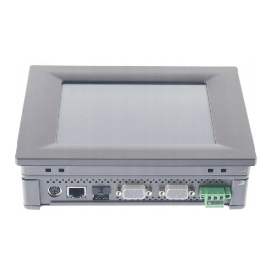
1.4 I/O Arrangement The I/O arrangement of the TPC-650 is as shown below: Fig.1-1: I/O arrangement TPC-650 User's Manual... -
Page 15: Dimensions/Cutout
DIP switches, which are accessible through the two openings on the rear cover. Before attaching connectors, please make sure the DIP switches settings are correct. (See Table 3.4-3) 1.5 Dimensions/Cutout Figure 1-2: TPC-650 front/bottom/side view and cutout Chapter 1 General Information... - Page 16 TPC-650 User's Manual...
-
Page 17: Chapter 2 System Setup
System Setup This chapter explains how to set up the TPC-650 hardware. Sections include: • General • Quick Start • Installing a CompactFlash™ Memory card • Installing a PC/104 Module • Connecting the Power Adapter • LCD Contrast (for TPC-650S only) •... -
Page 18: General
The TPC-650 is easily customizable to fulfill your needs. The kernel modules are accessible when the front bezel is removed. Warning! -
Page 19: Figure 2-2: Plug In The Compactflash™ Card
Step 2: Plug in the CompactFlash™ card (refer to section 2.3). Figure 2-2: Plug in the CompactFlash™ card Step 3: Install the PC/104 boards (refer to section 2.4) Figure 2-3: Install PC/104 boards Chapter 2 System Startup... -
Page 20: Figure 2-4: Connect Power Line (Including The Ground)
Step 4: Connect the power line and ground. (refer to section 2.5) Figure 2-4: Connect power line (including the ground) Step 5: Turn on the power switch Figure 2-5: Turn on the power tPC-650 User's Manual... -
Page 21: Figure 2-6: Adjusting Lcd Contrast
Step 6: Adjust the LCD contrast (refer to section 2.6) Figure 2-6: Adjusting LCD contrast Step 7: Calibrate the touchscreen. (refer to section 2.7). Chapter 2 System Startup... -
Page 22: Installing And Ejecting A Compactflash™ Memory Card
2.3 Installing and Ejecting a Compact- Flash™ Memory Card CompactFlash™ memory cards are the TPC-650's standard storage device. To insert and remove the memory card, do the following: Insert CompactFlash™ card into TPC-650 1.Check the CompactFlash™ shielding door latch. If it is locked, slide it to unlock position. -
Page 23: Installing A Pc/104 Module
Using these modules will save you space and valuable slots. To install a PC/104 module: 1.Verify that the power source to the TPC-650 has been properly dis- connected. 2.Plug the PC/104 module's male connectors into the ISA expansion slot's female connectors by pressing the module firmly with caution. -
Page 24: Connecting The Power Adapter
24V power receptable located on the rear side of the TPC-650. After the power terminal block has been attached, you can then connect the power adapter to the power terminal block to provide power supplies to your TPC-650. -
Page 25: Figure 2-9: Connecting The Power Adapter
Figure 2-9: Connecting the power adapter Note: The power terminal block is in the accessory pack shipped together with the TPC-650. However, the power adapter is an optional item to TPC-650. You can purchase it from Advantech separately, or find it from another vendor. Warning: Avoiding shorting any bare wires since it may cause damages to your system or device. -
Page 26: Adjusting Lcd Contrast (For Tpc-650S Only)
2.7 Touchscreen Calibration If the optional Windows CE OS or Advantech HMI software package ® is purchased with the TPC-650, you will find a touchscreen driver which can calibrate its sensitivity: 1. Click Start/Settings 2. Click Control Panel 3. The Control Panel window pops out. Double click touchscreen icon. -
Page 27: First System Boot
Communication Properties page. 2.Select the Device Name tab on the properties page, and assign a device name to your TPC-650. The Device Name is what comes to distinguish your TPC-650 within the network environment. 3.Click on OK to accept the Device Name setting. -
Page 28: Exploded Diagram
Otherwise all parameters will restore to default after system reboot. 2.9 Exploded Diagram The following exploded diagram is provided to help with assembly or disassembly of the TPC-650. Figure 2-11: Exploded diagram tPC-650 User's Manual... -
Page 29: Chapter 3 Tpc-650 Kernel: Pcm-9450 2
TPC-650 Kernel: PCM-9450 The heart of the TPC-650 is composed of two boards:the Advantech PCM-9450 main board and the PCM-9450 I/O board. The specifications for both are in this chapter. -
Page 30: Introduction
3.1 Introduction The heart of the TPC-650 is composed of two boards: the Advantech PCM-9450 main board and the PCM-9450 I/O board. This combination is designed to fit the TPC-650 form factor, and provides excellent quality and performance in Human Machine Interface or Operator Interface Terminal applications. -
Page 31: Pcm-9450 Main Board Specifications
Table 3-1 Connectors and jumpers Name Function IDE connector PC/104 connector 24-bit LCD interface 36-bit LCD interface LCD inverter power connector CN13 ATX connector CN16 Touchscreen interface LCD type selector Clear CMOS switch Standby 5V, VCC 5V switch Chapter 3 TPC-650 Kernel... -
Page 32: Figure 3-1: Pcm-9450 Main Board
Figure 3-1: PCM-9450 main board TPC-650 User's Manual... -
Page 33: Table 3-2: Cn1 Pin Assignment (Ide Connector)
DDP3 DAP2 DDP4 IDEACK0# DDP5 IRQ1 DDP6 IRQ8 DDP7 KBRESET# DDP8 A20GATE DDP9 24MHZ DDP10 PS_ON# DDP11 5VSB DDP12 DDP13 IDERSTP# DDP14 PIIX_RI# DDP15 IDEIORDY0 IDEIOR0# IDEDRQ0 IDEIOW0# IDELED0 IDEIRQ0# ENVEE TDP1 TDN1 RDP1 RDN1 VEEO_2 Chapter 3 TPC-650 Kernel... -
Page 34: Table 3-3: Cn2 Pin Assignment (Pc/104 Connector)
DACK6# SA17 IOR# SD10 DRQ6 SA16 DACK3# SD11 DACK7# SA15 DRQ3 SD12 DRQ7 SA14 DACK1# SD13 +5 V SA13 DRQ1 SD14 MASTER# SA12 REFRESH# SD15 SA11 SYSCLK SA10 IRQ7 — — IRQ6 — — IRQ5 — — TPC-650 User's Manual... - Page 35 IRQ4 — — IRQ3 — — DACK2# — — — —- BALE — — +5 V — — — — — — — — # low active Chapter 3 TPC-650 Kernel...
-
Page 36: Table 3-4: Cn5/Cn6 Pin Assignment (24-Bit/36-Bit Lcd Interface)
Table 3-4: CN5/CN6 pin assignment (24-bit/36-bit LCD interface) 1 3..37 39 O O O..O O O O O O..O O O 4..38 40 24-bit LCD display connector (CN5) Signal Signal VDDSAFE5 VDDSAFE5 VDDSAFE3 VDDSAFE3 Vcon SHIFT CLOCK FILM ENAVEE TPC-650 User's Manual... -
Page 37: Table 3-5: Cn7 Pin Assignment (Lcd Inverter Power Connector)
O O O..O O O 4..18 20 36-bit LCD display connector (CN6) Signal Signal ENABKL 1 2 3 4 5 O O O O O Table 3-5: CN7 pin assignment (LCD inverter power connector) Signal +12 V ENABKL +5 V Chapter 3 TPC-650 Kernel... -
Page 38: Table 3-6: Cn13 Pin Assignment (Atx Connector)
1 3 5 7 O O O O O O O O 2 4 6 8 Table 3-8: JP2 pin assignment (LCD type selector) Signal Signal MMA3 MMA4 MMA5 MMA6 FOR PRIMEVIEW 6.4" 3-4,7-8 FOR KYOCERA 5.7" 1-2,5-6,7-8 TPC-650 User's Manual... -
Page 39: Table 3-9: Jp3 Pin Assignment (Clear Cmos Switch)
Table 3-9: JP3 pin assignment (Clear CMOS switch) Signal VBAT3V_IN VBAT3V 1-2: NORMAL 2-3: CLEAR CMOS 1 2 3 O O O Table 3-10: JP5 pin assignment (Standby 5V & Vcc 5V switch) Signal STB5V STB5V_VCC 1-2: STANT BY 5V 2-3: VCC 5V Chapter 3 TPC-650 Kernel... - Page 40 3.4 PCM-9450 I/O Board Specifications Figure 3-1: PCM-9450 I/O board...
- Page 41 Table 3-11: Jumpers and connectors Name Function LCD power switch connector COM2 selector switch 1 COM2 selector switch 2 CompactFlash™ socket DB-25 Parallel port Power connector Serial port RS-232 CN10 Serial port RS-232/422/485 RJ-45 Ethernet port PS/2 Keyboard/mouse connector 1 2 3 O O O Table 3-12: JP1 pin assignment (LCD power switch connector) Signal...
- Page 42 SW DIP-6 SW DIP-6 Figure 3-2: DIP switch setting Table 3-14: CN2 (CompactFlash™ socket) Signal Signal CS0# A10 2 ATA SEL A09 2 A07 2 A06 2 A04 2 -IOCS16 -CD2 -CD1 D141 -CS1 -VS1 -IORD -IOWR 36 -WE INTRQ 38 V CC -CSEL -VS2...
- Page 43 13 12 O O O O ..O O O ... O O O 14 15 Table 3-15: CN7 (Parallel port) Signal Signal STROBE# AUTOFD# INIT# SLCTINI# ACK# BUSY SLCT Table 3-16: CN8 (Power connector) +24V...
- Page 44 6 7 8 9 O O O O O O O O O 1 2 3 4 5 Table 3-17: CN9 (Serial port RS-232) Pin Signal 6 7 8 9 O O O O O O O O O 1 2 3 4 5 Table 3-18: CN10 (Serial port RS-232/422/485) RS-232 port RS-422 port...
- Page 45 O O O O O O O O 1 2 3 4 5 6 7 8 Table 3-19: RJ-45 (Ethernet port) Signal • Table 3-20: PS/2 (Keyboard/mouse connector) Signal KB DATA MS DATA V CC KB CLOCK MS CLOCK...
-
Page 46: Safety Precautions
3.5 Safety Precautions Warning! Always completely disconnect the power cord from your chassis whenever you are working on it. Do not make connections while the power is on, because sensitive electronic components can be damaged by the sudden rush of power. Only experienced electron- ics personnel should open the PC chassis. -
Page 47: Setting Jumpers
3.6 Setting Jumpers You may configure your card to match the needs of your application by setting jumpers. A jumper is a metal bridge that closes an electrical circuit. It consists of two metal pins and a small metal clip (often protected by a plastic cover) that slides over the pins to connect them. -
Page 48: Chapter 4 Networking Communication
Networking Communication This chapter describes the ways to get your TPC-650 connected to the host PC. Sections include: • Introduction • Networking via LAN • Networking via RS-232 • Simple Networking via a Hub... -
Page 49: Introduction
If you have not installed the TCP/IP network protocol on your host PC, you must install it first before joining the host PC to the Ethernet LAN. 2. Make sure your TPC-650 is running an OS that has its TCP/IP network protocol enabled. Note: If you use a CompactFlash™... - Page 50 4. Use a twisted-pair UTP or STP cable (category 3, 4, 5) to connect the TPC-650 through its RJ-45 port to a hub (or a switch) within the Ethernet LAN to which your host PC is also connected. 5. Assign valid IP addresses for your TPC-650 and host PC. If you are joining an existing Intranet, ask your network administrator for valid IP addresses.
-
Page 51: Networking Via Rs-232
If you have not installed the RAS, you must install it on your system. 2. Use the DB-9 NULL modem cable (that accompanies your TPC-650) to connect the TPC-650 through its RS-232 port to the COM port of your host PC. TPC-650 User's Manual... -
Page 52: Simple Networking Via A Hub
PC. 4.4 Simple Networking via a Hub If you want to connect your TPC-650 and the host PC only through RJ-45 ports, you must use twisted-pair cables to connect both to a central hub. Note that this network configuration is essentially the same as Ethernet, despite a configuration of merely two end nodes. - Page 53 TPC-650 User's Manual...
-
Page 54: Chapter 5 Mounting
Mounting This chapter describes the ways to mount your TPC-650. - Page 55 If you want to panel mount your TPC-650, use the four brackets that are included within your package. First, fit the TPC-650 body onto the cutout panel and hold it temporarily in place with your hands. Then, insert each bracket into the four keyholes on both sides of the TPC- 650 rear case, and use appropriate screws to fix the TPC-650 body on the cutout panel.
-
Page 56: Programming The Watchdog Timer
Programming the Watchdog Timer The TPC-650 is equipped with a watchdog timer that resets the CPU or generates an interrupt if process- ing comes to a standstill for any reason. This feature ensures system reliability in industrial standalone or unmanned environments. -
Page 57: A.1 Programming The Watchdog Timer
01 (hex) to 3F (hex), and the related time interval is 1 sec. to 63 sec. Data Time Interval 1 sec. 2 sec. 3 sec. 4 sec. • • • • • • 63 sec. TPC-650 User's Manual... - Page 58 After data entry, your program must refresh the watchdog timer by rewriting I/O port 443 (hex) while simultaneously setting it. When you want to disable the watchdog timer, your program should read I/O port 443 (hex). The following example shows how you might program the watchdog timer in BASIC: REM Watchdog timer example program OUT &H443, data REM Start and restart the watchdog...
- Page 59 TPC-650 User's Manual...
- Page 60 Cabling for RS- 232 Port The TPC-650 is equipped with a watchdog timer that resets the CPU if processing comes to a standstill for any reason. This feature ensures system reliability in industrial standalone or unmanned environments.
- Page 61 The TPC-650 is shipped together with a serial cable (NULL modem cable) for customers to make a direct connection between it and the host PC. Note that off-the-shelf NULL modem cables may not be wired correctly. The following is a wiring table for this cable:...
-
Page 62: Appendix B Cabling For Rs-232 Port
25-pin NULL Modem Cable: i r r Appendix B Cabling for RS-232 Port...
Need help?
Do you have a question about the TPC-650 and is the answer not in the manual?
Questions and answers