Advertisement
Quick Links
THEVA1027D-V1_User's Guide_Rev.1.00_E
THC63LVD1027D Evaluation Kit
1. General Description
THEVA1027D-V1 is designed to evaluate THC63LVD1027D for transmission video data.
THC63LVD1027D chipset can transmit 35bit data via dual channel LVDS.
The maximum input clock frequency of THC63LVD1027D is 150MHz.
2. Features
THC63LVD1027D
・Low power single 3.3V CMOS design
・Power down mode
・Wide dot clock range suited for Flat Panel Display up to WUXGA resolution
・PLL requires no external components
・Single/Dual LVDS (Open-LDI) in, Single/Dual LVDS (Open-LDI) out
・Distribution signal duplication mode
・Support Reduced Swing LVDS for Lower EMI
・64 Pin TSSOP with Exposed PAD (0.5mm lead pitch)
3. Overview
Copyright(C) 2016 THine Electronics, Inc.
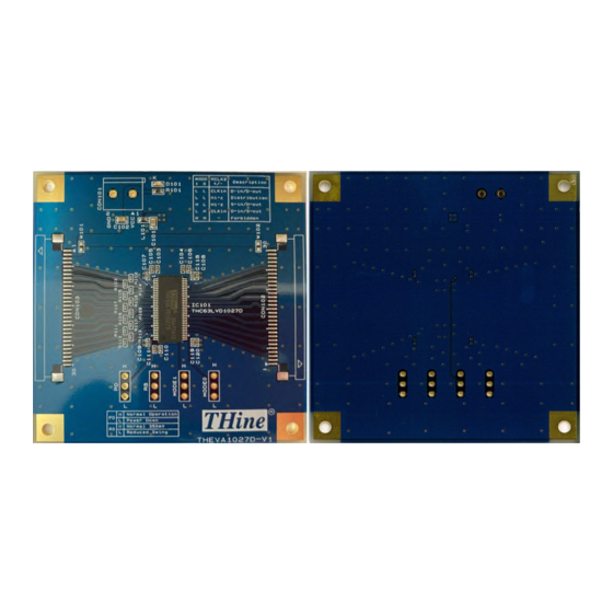
LVDS Dual Link Evaluation Board
Parts Number: THEVA1027D-V1
Figure 1 THEVA1027D-V1
1/7
THine Electronics, Inc.
SC: E
Advertisement

Related Manuals for THine THC63LVD1027D


Summary of Contents for THine THC63LVD1027D
- Page 1 LVDS Dual Link Evaluation Board Parts Number: THEVA1027D-V1 1. General Description THEVA1027D-V1 is designed to evaluate THC63LVD1027D for transmission video data. THC63LVD1027D chipset can transmit 35bit data via dual channel LVDS. The maximum input clock frequency of THC63LVD1027D is 150MHz.
-
Page 2: Power Supply Setup
W101: Connect the 3.3V power supply with pin#1 and 2 of CON103. W102: Connect the 3.3V power supply with pin#29 and 30 of CON102. Figure 3 THEVA1027D-V1 power supply from / to each connector THine Electronics, Inc. Copyright(C) 2022 THine Electronics, Inc. SC: E... -
Page 3: Function Setting
Each setting pin’s high or low setting can set by connecting pin#2 of 3HEADER and high level or low level. (a)3HEADER Description (b)High Level Setting (c)Low Level Setting Figure 5 Schematic diagram of High / Low setting description 6. Status Indicate LED LED “D101” indicates 3.3V power supply status. THine Electronics, Inc. Copyright(C) 2022 THine Electronics, Inc. SC: E... - Page 4 Pixel data mode select MODE1 MODE1 MODE1 MODE0 RCLK2+/- Function Clock input Dual-in / Dual -out Hi-Z Distribution Hi-Z Single-in / Dual -out MODE0 MODE0 Clock input Dual-in / Single-out Reserved THine Electronics, Inc. Copyright(C) 2022 THine Electronics, Inc. SC: E...
- Page 5 THEVA1027D-V1_User's Guide_Rev.1.00_E 8. Schematic Figure 6 THEVA1027D-V1 Schematic THine Electronics, Inc. Copyright(C) 2022 THine Electronics, Inc. SC: E...
-
Page 6: Bills Of Materials
Part No. DC Connector 282836-2 FFC Connector for LVDS Link 52271-3069 FFC 30pin 1mm Pitch for LVDS Link 98267-0475 It’s possible to mount these parts on this board and use. THine Electronics, Inc. Copyright(C) 2022 THine Electronics, Inc. SC: E... - Page 7 Therefore, customers are encouraged to have sufficiently redundant or error-preventive design applied to the use of the product so as not to have THine’s product cause any social or public damage. Neither replacement nor failure analysis of the product is available in any case of defects with the product and/or the product’s components.
Need help?
Do you have a question about the THC63LVD1027D and is the answer not in the manual?
Questions and answers