Table of Contents
Advertisement
Quick Links
THAN0210_Rev.1.00_E
THC63LVD827(-Q) Evaluation Kit
1. General Description
THEVA827 is designed to evaluate THC63LVD827(-Q) for transmission video data.
THC63LVD827(-Q) chipset can transmit 24bit RGB data and HS/VS/DE sync via dual channel LVDS.
The maximum clock frequency of THC63LVD827(-Q) is 174MHz.
2. Features
THC63LVD827
・Low power 1.8V CMOS design (1.8~3.3V IO voltage supported)
・Power down mode
・Wide dot clock range suited for TV signal(480i to 1080p), PC signal(VGA to WUXGA)
・PLL requires no external components
・Clock edge selectable
・Single TTL in, Single/Dual LVDS (Open-LDI) out
・Double Edge Input(Single in/Dual out Mode)
・Additional 6bit only low power mode
・2 LVDS Data Mapping Modes
・Pseudo Random Pattern Generation Circuit
・Support Reduced Swing LVDS for Lower EMI
・TFBGA 72 Pin 7x7mm 0.65mm pitch
3. Overview
Copyright(C) 2016 THine Electronics, Inc.
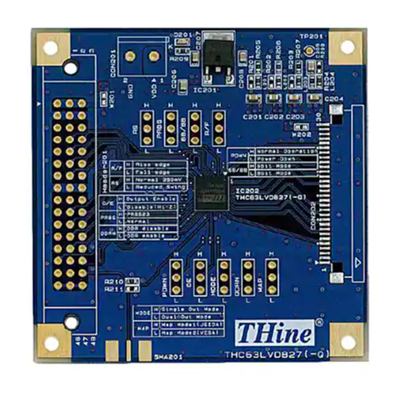
LVDS Dual Link Evaluation Board
Parts Number: THEVA827
Figure 1 THEVA827
1/7
THine Electronics, Inc.
Security E
Advertisement
Table of Contents

Related Manuals for THine THEVA827


Summary of Contents for THine THEVA827
- Page 1 LVDS Dual Link Evaluation Board Parts Number: THEVA827 1. General Description THEVA827 is designed to evaluate THC63LVD827(-Q) for transmission video data. THC63LVD827(-Q) chipset can transmit 24bit RGB data and HS/VS/DE sync via dual channel LVDS. The maximum clock frequency of THC63LVD827(-Q) is 174MHz.
- Page 2 W201: Connect the power supply with pin#1, 2 and 3 of Header201. W202: Connect the power supply with pin#29 and 30 of CON202. Figure 3 THEVA827 power supply from / to each Connector THine Electronics, Inc. Copyright(C) 2016 THine Electronics, Inc.
- Page 3 6. Clock Input from SMA Connector THEVA827 can also choose the TTL clock input from SMA connector by using 0ohm resistor. If you want to use SMA connector for clock input, please change the 0ohm resistor mount from R210 to R211.
- Page 4 THAN0210_Rev.1.00_E 7. Status Indicate LED LED “D201” indicates power supply status. 8. Function This chapter shows function setting of THEVA827. Table 1 THEVA827 Function Setting Description Silk Symbol Function Input clock triggering edge select. H : Rising Edge L : Falling Edge LVDS swing mode, VREF select.
- Page 5 THAN0210_Rev.1.00_E 9. Schematic Figure 7 THEVA827 Schematic THine Electronics, Inc. Copyright(C) 2016 THine Electronics, Inc. Security E...
- Page 6 THAN0210_Rev.1.00_E 10. Bill of Materials Table 2 THEVA827 BOM Comment Description Value Note Designator Q'ty C201, C202, C203, C204, C205, C206, C207, Capacitor2012 2012 10uF C208 Capacitor1005 1005 0.01uF C209, C211, C213, C215, C217, C219 Capacitor1005 1005 0.1uF C210, C212, C214, C216, C218, C220...
- Page 7 THine’s product cause any social or public damage. Replacement of the product is only available in case of obvious defects of mount devices at the point of unpacking the product. Neither replacement nor failure analysis of the product is available in any other case of defects with the product and/or the product’s components.
Need help?
Do you have a question about the THEVA827 and is the answer not in the manual?
Questions and answers