Table of Contents
Advertisement
Quick Links
ROCKY- 4784EVG Series
SOCKET 478 PENTIUM 4 with
10/100M LAN & Gigabit LAN &
SiS 315 AGP4X VGA SBC
Ver 1.1
Manual Reversion 1.1
April. 10, 2003
@Copyright 2001
All Rights Reserved.
The information in this document is subject to change without prior notice in
order to improve reliability, design and function and does not represent a
commitment on the part of the manufacturer.
In no event will the manufacturer be liable for direct, indirect, special,
incidental, or consequential damages arising out of the use or inability to use
the product or documentation, even if advised of the possibility of such
damages.
This document contains proprietary information protected by copyright. All
rights are reserved. No part of this manual may be reproduced by any
mechanical, electronic, or other means in any form without prior written
permission of the manufacturer.
Trademarks
ROCKY-4784EVG is registered trademarks of ICP Electronics Inc.; IBM PC is
a registered trademark of International Business Machines Corporation. Intel is
a registered trademark of Intel Corporation. AWARD is registered trademarks
of AWARD Software ,Inc.. Other product names mentioned herein are used for
identification purposes only and may be trademarks and/or registered
trademarks of their respective companies.
Support
Any questions regarding the content of this manual or related issues can be e-
SUPPORT@IEI.COM.TW
mailed to us directly at:
Advertisement
Table of Contents

Subscribe to Our Youtube Channel
Related Manuals for ICP Electronics IEI ROCKY- 4784EVG Series


Summary of Contents for ICP Electronics IEI ROCKY- 4784EVG Series
- Page 1 Trademarks ROCKY-4784EVG is registered trademarks of ICP Electronics Inc.; IBM PC is a registered trademark of International Business Machines Corporation. Intel is a registered trademark of Intel Corporation. AWARD is registered trademarks of AWARD Software ,Inc..
-
Page 3: Table Of Contents
Contents 1. Introduction ..............3 Specifications..................... 4 What You Have..................6 2. Installation..............7 ROCKY – 4784EVG's Layout ..............8 Unpacking Precautions ................9 Clear CMOS Setup .................. 10 CompactFlash Master/Slave Setting ............10 Onboard Keyboard/Mouse Source Setting..........10 3. Connection ..............11 Floppy Disk Drive Connector .............. - Page 4 3.12 AUDIO Headphone & Input Connector ..........19 3.13 ATX 20-PIN Power Connector..............19 4. AWARD BIOS Setup ........20 Introduction ..................20 Starting Setup ................20 Using Setup ...................21 Getting Help ...................22 Main Menu ..................23 Standard CMOS Setup ..............26 Advanced BIOS Features Setup ............30 Advanced Chipset Features Setup ..........34 Integrated Peripherals Setup ............36 4.10...
-
Page 5: Introduction
Introduction Welcome to the ROCKY-4784EVG SOCKET 478 PENTIUM 4 Single Board Computer. The ROCKY-4784EVG board is an ISA/PCI form factor board, which comes equipped with high performance Processor and advanced high performance multi- mode I/O, designed for the system manufacturers, integrators, or VARs that want to provide all the performance, reliability, and quality at a reasonable price. -
Page 6: Specifications
Specifications Intel Pentium 4 Processor, supports 400/533 MHz CPU(PGA 478) Bus interface PCI/ISA bus, PICMG compliant Bus speed ISA : 8MHz, PCI: 33MHz DMA channels Interrupt levels Chipset INTEL 845E (MCH) Real-time INTEL 82801BA(ICH2) clock/calendar TWO 184-pin DIMM sockets support DDR RAM memory SDRAM . - Page 7 USB port Supports 2 USB ports for future expansion Software Programmable Reset generated when Watch-dog CPU does not periodically trigger the timer. Your timer can use I/O Port hex 043(843) & 443 to control the watchdog and generate a system reset. On Board SiS 315 AGP4X 256-bit 3D graphics engine.
-
Page 8: What You Have
What You Have In addition to this User's Manual, the ROCKY-4784EVG package includes the following items: One ROCKY-4784EVG Single Board Computer • • One RS-232 x2 and Printer Cable with bracket • One FDD cable • One ATA/100 IDE cables. •... -
Page 9: Installation
Installation This chapter describes how to install the ROCKY-4784EVG. At first, the layout of ROCKY-4784EVG is shown, and the unpacking information that you should be careful is described. The jumpers and switches setting for the ROCKY-4784EVG's configuration, such as CPU clock setting, and watchdog timer, are also included. -
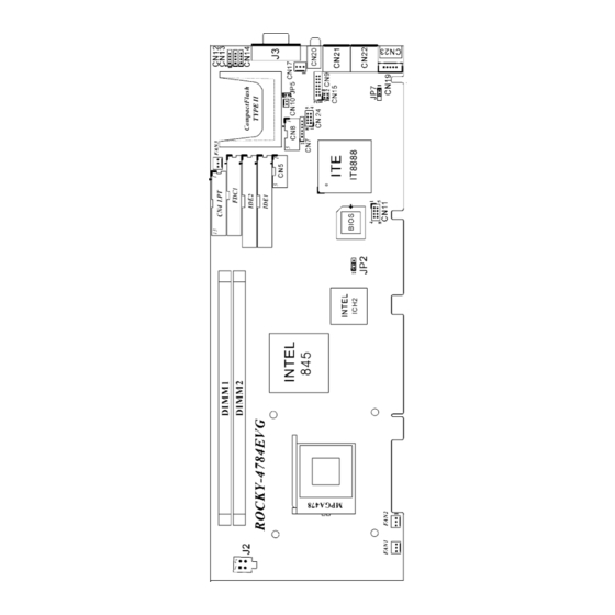
Page 10: Rocky - 4784Evg's Layout
ROCKY – 4784EVG's Layout... -
Page 11: Unpacking Precautions
Unpacking Precautions Some components on ROCKY-4784EVG SBC are very sensitive to static electric charges and can be damaged by a sudden rush of power. To protect it from unintended damage, be sure to follow these precautions: Ground yourself to remove any static charge before touching your ROCKY-4784EVG SBC. -
Page 12: Clear Cmos Setup
Clear CMOS Setup If want to clear the CMOS Setup (for example forgot the password you should clear the setup and then set the password again.), you should close the JP2 (2-3) about 3 seconds, then open it again. Set back to normal operation mode, open JP2. •... -
Page 13: Connection
Connection This chapter describes how to connect peripherals, switches and indicators to the ROCKY- 4784EVG board. Table of Connectors LABEL FUNCTION FAN1~FAN3 Fan Connectors ATX-12V CPU Power Source VGA 15-pin Female Connector IrDA connector CN10 ATX BUTTON (Power ON) Switch CN11 USB Connectors Parallel Port Connector... -
Page 14: Floppy Disk Drive Connector
Floppy Disk Drive Connector The ROCKY-4784EVG board is equipped with a 34-pin daisy- chain drive connector cable. • FDC1 : FDC Connector PIN NO. DESCRIPTION PIN NO. DESCRIPTION GROUND REDUCE WRITE GROUND GROUND GROUND INDEX# GROUND MOTOR ENABLE A# GROUND DRIVE SELECT B# GROUND DRIVE SELECT A#... -
Page 15: Pci E-Ide Disk Drive Connector
PCI E-IDE Disk Drive Connector You can attach four IDE( Integrated Device Electronics) hard disk drives on two channels. These connectors support Ultra- DMA100 IDE devices. Non-DMA100 devices are suggested to be connecting to the secondary IDE connector. IDE 1 : Primary IDE Connector IDE 2 : Secondary IDE Connector •... -
Page 16: Parallel Port
Parallel Port This port is usually connected to a printer. The ROCKY- 4784EVG includes an on-board parallel port, accessed through a 26-pin flat-cable connector. • CN4 : Parallel Port Connector PIN NO. DESCRIPTION PIN NO. DESCRIPTION STROBE# DATA 0 DATA 1 DATA 2 DATA 3 DATA 4... -
Page 17: Keyboard & Ps/2 Mouse Connector
• Serial Port 10-pin Connector PIN NO. DESCRIPTION DATA CARRIER DETECT (DCD) RECEIVE DATA (RXD) TRANSMIT DATA (TXD) DATA TERMINAL READY (DTR) GROUND (GND) DATA SET READY (DSR) REQUEST TO SEND (RTS) CLEAR TO SEND (CTS) RING INDICATOR (RI) GROUND (GND) Keyboard &... -
Page 18: External Switches And Indicators
External Switches and Indicators There are several external switches and indicators for monitoring and controlling your CPU board. All the functions are in the CN9 connector. CN9 : External Switches and Indicators PIN DESCRIPTION PIN DESCRIPTION Speaker Power Speaker KeylLock+ LOCK KeyLock- Reset Switch... -
Page 19: Usb Port Connector
USB Port Connector The ROCKY- 4784EVG provide 4 built-in USB ports for the future new I/O bus expansion. CN11 PIN NO. DESCRIPTION DESCRIPTION GROUND DATA- DATA+ DATA+ DATA- GROUND IrDA Infrared Interface Port The ROCKY-4784EVG has a built-in IrDA port which supports Serial Infrared (SIR) or Amplitude Shift Keyed IR (ASKIR) interface. -
Page 20: Lan Rj45 & State Led Connector
3.10 LAN RJ45& State LED Connectors The ROCKY-4784EVG is equipped with built-in 10/100Mbps & 10/100/1000Mbps Ethernet controllers. You can connect it to your LAN through RJ45 LAN connectors. There are two LED on the connector indicating the status of LAN. The pin assignments are as following: (CN21:ICH2 / CN22:BCM5702) •... -
Page 21: Audio Headphone & Input Connector
3.12 AUDIO Headphone & Connector The ROCKY-4784EVG has a built-in AC’97 AUDIO CODEC; connector directly connects to your MIC-IN & CD-IN & LINE-IN. • CN20: AUDIO Headphone Jack (Output) • CN12: AUDIO LINE-IN Connector (Input) • CN13: AUDIO CD-IN Connector (Input) •... -
Page 22: Award Bios Setup
AWARD BIOS SETUP Introduction This manual discusses Award's Setup program built into the ROM BIOS. The Setup program allows users to modify the basic system configuration. This special information is then stored in battery-backed RAM so that it retains the Setup information when the power is turned off. Starting Setup The Award BIOS is immediately activated when you first power on the computer.The BIOS reads the system information contained in the... -
Page 23: Using Setup
PRESS F1 TO CONTINUE, DEL TO ENTER SETUP 4.3 Using Setup In general, you use the arrow keys to highlight items, press <Enter> to select, use the PageUp and PageDown keys to change entries, press <F1> for help and press <Esc> to quit. The following table provides more detail about how to navigate in the Setup program using the keyboard. -
Page 24: Getting Help
4.4 Getting Help Press F1 to pop up a small help window that describes the appropriate keys to use and the possible selections for the highlighted item. To exit the Help Window press <Esc> or the F1 key again. If, after making and saving system changes with Setup, you discover that your computer no longer is able to boot, the Award BIOS supports an override to the CMOS settings which resets your system to its defaults. -
Page 25: Main Menu
4.5 Main Menu Once you enter the AwardBIOS™ CMOS Setup Utility, the Main Menu will appear on the screen. The Main Menu allows you to select from several setup functions and two exit choices. Use the arrow keys to select among the items and press <Enter> to accept and enter the sub- menu. - Page 26 Standard CMOS Features Use this menu for basic system configuration. See Section 4.6 for the details. Advanced BIOS Features Use this menu to set the Advanced Features available on your system. See Section 4.7 for the details. Advanced Chipset Features Use this menu to change the values in the chipset registers and optimize your system's performance.
- Page 27 Frequency/Voltage Control Use this menu to specify your settings for frequency/voltage control. See section 4.13 for the details. Load Fail-Safe Defaults Use this menu to load the BIOS default values for the minimal/stable performance for your system to operate. See section 4.14 for the details. Load Optimized Defaults Use this menu to load the BIOS default values that are factory settings for optimal performance system operations.
-
Page 28: Standard Cmos Setup
4.6 Standard CMOS Setup The items in Standard CMOS Setup Menu are divided into 10 categories. Each category includes no, one or more than one setup items. Use the arrow keys to highlight the item and then use the <PgUp> or <PgDn> keys to select the value you want in each item. - Page 29 Main Menu Selections Item Options Description Date MM DD YYYY Set the system date. Time HH : MM : SS Set the system time Options are in its sub Press <Enter> to enter Primary Master menu the sub menu of detailed (described in Table 3) options Options are in its sub...
- Page 30 IDE Adapters The IDE adapters control the hard disk drive. Use a separate sub menu to configure each hard disk drive. Figure 2 shows the IDE primary master sub menu. CMOS Setup Utility - Copyright ( C ) 1984-2001 Award Software IDE Primary Master IDE HDD Auto-Detection Press Enter...
- Page 31 Use the legend keys to navigate through this menu and exit to the main menu. Use Table 3 to configure the hard disk. Item Options Description IDE HDD Auto-detection Press Enter Press Enter to auto-detect the HDD on this channel. If detection is successful, it fills the remaining fields on this menu.
-
Page 32: Advanced Bios Features Setup
4.7 Advanced BIOS Features This section allows you to configure your system for basic operation. You have the opportunity to select the system’s default speed, boot-up sequence, keyboard operation, shadowing and security. CMOS Setup Utility - Copyright ( C ) 1984-2001 Award Software Advanced BIOS Features Virus Warning Disabled... - Page 33 Virus Warning Allows you to choose the VIRUS Warning feature for IDE Hard Disk boot sector protection. If this function is enabled and someone attempt to write data into this area, BIOS will show a warning message on screen and alarm beep. Enabled Activates automatically when the system boots up causing a warning message to appear when anything...
- Page 34 First/Second/Third/Other Boot Device The BIOS attempts to load the operating system from the devices in the sequence selected in these items. The Choice: Floppy, LS/ZIP, HDD, SCSI, CDROM, Disabled. Swap Floppy Drive If the system has two floppy drives, you can swap the logical drive name assignments.
- Page 35 Typematic Delay (Msec) Sets the delay time after the key is held down before it begins to repeat the keystroke. The choice: 250, 500, 750, 1000. Security Option Select whether the password is required every time the system boots or only when you enter setup.
-
Page 36: Advanced Chipset Features Setup
4.8 Advanced Chipset Features CMOS Setup Utility - Copyright ( C ) 1984-2001 Award Software Advanced Chipset Features DRAM Timing Selectable Item Help CAS Latency Time ______________________ Active to Precharge Delay DRAM RAS# TO CAS# Delay Menu Level DRAM RAS# Precharge Memory Frequency For Auto System BIOS Cacheable... - Page 37 CAS Latency Time When synchronous DRAM is installed, the number of clock cycles of CAS latency depends on the DRAM timing. Do not reset this field from the default value The Choice: 2, 3. specified by the system designer. Memory Frequency For Auto: by hardware.
-
Page 38: Integrated Peripherals Setup
4.9 Integrated Peripherals CMOS Setup Utility – Copyright © 1984 – 2001 Award Software Integrated Peripherals Onboard LAN(10/100/1000) [Enabled] Item Help Onboard VGA Device [Enabled] ____________________ On-Chip Primary PCI IDE [Enabled] Menu Level IDE Primary Master PIO [ Auto] If your IDE hard drive IDE Primary Slave PIO [Auto] supports block mode select... - Page 39 On-Chip Primary PCI IDE The chipset contains a PCI IDE interface with support for two IDE channels. Select Enabled to activate the primary IDE interface. Select Disabled to deactivate this interface The choice: Enabled, Disabled. Primary/Secondary Master/Slave PIO The four IDE PIO (Programmed Input/Output) fields let you set a PIO mode (0-4) for each of the four IDE devices that the onboard IDE interface supports.
- Page 40 Onboard FDC Controller Select Enabled if your system has a floppy disk controller (FDC) installed on the system board and you wish to use it. If you install and-in FDC or the system has no floppy drive, select Disabled in this field. OnChip USB This should be enabled if your system has a USB installed on the system board and you want to use it.
- Page 41 Parallel Port Mode Select an operating mode for the onboard parallel (printer) port. Select Normal, Compatible, or SPP unless you are certain your hardware and software both support one of the other available modes. The choice: Normal, EPP, ECP,ECP/EPP ECP Mode Use DMA Select a DMA channel for the parallel port for use during ECP mode.
-
Page 42: Power Management Setup
4.10 Power Management Setup The Power Management Setup allows you to configure you system to most effectively save energy while operating in a manner consistent with your own style of computer use. CMOS Setup Utility – Copyright © 1984 – 2001 Award Software Power Management Setup ACPI function [Disabled]... - Page 43 ACPI Function This item allows you to enable/disable the Advanced Configuration and Power Management (ACPI). The choice: Enabled, Disabled. Power Management This category allows you to select the type (or degree) of power saving and is directly related to the following modes: 1.
- Page 44 Video Off In suspend When enabled, this feature allows the VGA adapter to operate in a power saving mode. Monitor will remain on during power saving modes. Monitor blanked when the systems enters the Suspend mode. Video Off Method This determines the manner in which the monitor is blanked. V/H SYNC+Blank This selection will cause the system to turn off the vertical and horizontal synchronization ports and...
- Page 45 configured as On, even when the system is in a power down mode. Power On by Ring An input signal on the serial Ring Indicator (RI) line (in other words, an incoming call on the modem) and LAN WOL awakens the system from a soft off state. Resume by Alarm When Enabled, your can set the date and time at which the RTC (real-time clock) alarm awakens the system from Suspend mode.
-
Page 46: Pnp/Pci Configuration Setup
4.11 PnP/PCI Configurations This section describes configuring the PCI bus system. PCI, or Personal Computer Interconnect, is a system which allows I/O devices to operate at speeds nearing the speed the CPU itself uses when communicating with its own special components. This section covers some very technical items and it is strongly recommended that only experienced users should make any changes to the default settings. - Page 47 Pnp OS Installed This item allows you to determine install PnP OS or not. The choice: Yes, No. Reset Configuration Data Normally, you leave this field Disabled. Select Enabled to reset Extended System Configuration Data (ESCD) when you exit Setup if you have installed a new add-on and the system reconfiguration has caused such a serious conflict that the operating system can not boot.
- Page 48 DMA Resource When resources are controlled manually, assign each system DMA channel a type, depending on the type of device using the DMA channel. DMA 0/1/3/5/6/7 assigned to Legacy ISA for devices compliant with the original PC AT bus specification, PCI/ISA PnP for devices compliant with the Plug and Play standard whether designed for PCI or ISA bus architecture.
-
Page 49: Pc Health Status Setup
4.12 PC Health Status CMOS Setup Utility – Copyright © 1984-2001 Award Software PC Health Status Item Help Current System1 Temp. 28℃ ------------------------- Current System2 Temp. 32℃ Menu Level Current CPU Temp 32℃ Current FAN1 Speed 5336RPM Current FAN2 Speed 5353RPM Current FAN3 Speed 5353RPM... -
Page 50: Frequency / Voltage Control Setup
4.13 Frequency/Voltage Control CMOS Setup Utility – Copyright © 1984-2001 Award Software Frequency/Voltage Control CPU Clock Ratio [8X] Item Help Auto Detect DIMM/PCI Clk [Disabled] ------------------------------------------------- Spread Spectrum [Disabled] Menu Level CPU HOST/SDRAM/PCI Clock [Default ] ↑↓←→ Move Enter: Select +/-/PU/PD: Value F10:Save ESC: Exit F1:General Help F5:Previous Values F6:Fail-safe defaults F7:Optimized Defaults... -
Page 51: Defaults Menu Setup
4.14 Defaults Menu Selecting “Defaults” from the main menu shows you two options which are described below Load Fail-Safe Defaults When you press <Enter> on this item you get a confirmation dialog box with a message similar to: Load Fail-Safe Defaults (Y/N) ? N Pressing ‘Y’... -
Page 52: Change Supervisor/User Password
4.15 Supervisor/User Password Setting You can set either supervisor or user password, or both of them. The differences between are: supervisor password : can enter and change the options of the setup menus. user password just can only enter but do not have the right to change the options of the setup menus. -
Page 53: Exit Selection
You determine when the password is required within the BIOS Features Setup Menu and its Security option (see Section 3). If the Security option is set to password will be required both at boot and at entry to Setup. If set to “Setup”, prompting only occurs when trying to enter Setup. -
Page 54: Appendix A. Watch-Dog Timer
Appendix A. Watch-Dog Timer The WatchDog Timer is a device to ensure that standalone systems can always recover from abnormal conditions that cause the system to crash. These conditions may result from an external EMI or a software bug. When the system stops working, hardware on the board will perform hardware reset (cold boot) to bring the system back to a known state. - Page 55 Example assembly program: TIMER_PORT = 443H TIMER_START = 443H TIMER_STOP = 843H ;;INITIAL TIMER COUNTER MOV DX, TIMER_PORT MOV AL, 8 ;;8 seconds OUT DX, AL MOV DX, TIMER_START IN AL, DX. ;;START COUNTER W_LOOP: MOV DX, TIMER_STOP IN AL, DX MOV DX, TIMER_START IN AL, DX ;;RESTART COUNTER...
-
Page 56: Appendix B. I/O Address Map
Appendix B. I/O Address Map • I/O Address Map I/O Address Description 000-01F DMA Controller #1 020-021 Interrupt Controller # 1, Master 040-05F System Timer 060-06F Standard 101/102 keyboard Controller 070-07F Real time Clock, NMI Controller 080-0BF DMA Page Register 0A0-0BF Interrupt Controller # 2 0C0-0DF... - Page 57 1 st MB Memory Address Map Memory address Description 00000-9FFFF SYSTEM MEMORY A0000-BFFFF VGA BUFFER C0000-CFFFF VGA BIOS E0000-FFFFF SYSTEM BIOS 100000 EXTEND MEMORY IRQ Mapping Chart IRQ0 System Timer IRQ8 RTC clock IRQ1 Keyboard IRQ9 IRQ FOR PCI STEERING IRQ2 IRQ Controller IRQ10 LAN IRQ3 COM2...
-
Page 58: Appendix C. Atx Power Supply
Appendix C. ATX Power Supply The following notes show how to connect ATX Power Supply to the backplanes and / or the ISBC card. A. For backplanes with ATX Connector Please, disconnect the AC cord of the Power Supply from the AC source to prevent sudden electric surge to the board. - Page 59 B. For the backplanes with ATX power supply connector For some SBC without ATX power ON/OFF function, then you can control the ATX power supply through backplane’s PS ON connector. Refer to the figure below: for the backplanes with ATX connector, the connection can be made simply as following: Connect the ON/OFF (ordinary one) switch to Pin 2 (PS ON) and Pin 3 (GND) of connector CN2...
-
Page 60: Appendix D. How To Use Wake Up Function
Appendix D. How to use Wake-Up Function The ROCKY-4784EVG provides two kind of Wake up Function. This page describes how to use Modem Wake-Up and LAN Wake-Up function. Wake-Up function is working while you use ATX power supply, Wake –Up On Modem(Ring) : You must set the option Wake-Up On LAN/Ring of CMOS SETUP to be enabled.
Need help?
Do you have a question about the IEI ROCKY- 4784EVG Series and is the answer not in the manual?
Questions and answers