Table of Contents
Advertisement
Quick Links
ROCKY-3742EVFG/EVF/EV
Dual Socket-370 Base CPU Board with
10/100Mb LAN, VGA, Audio, IEEE1394 &
Gigabit LAN,
Ver1.0
@Copyright 2001
All Rights Reserved.
Manual first edition Jan 14, 2001
The information in this document is subject to change without prior
notice in order to improve reliability, design and function and does
not represent a commitment on the part of the manufacturer.
In no event will the manufacturer be liable for direct, indirect, special,
incidental, or consequential damages arising out of the use or
inability to use the product or documentation, even if advised of the
possibility of such damages.
This document contains proprietary information protected by
copyright. All rights are reserved. No part of this manual may be
reproduced by any mechanical, electronic, or other means in any
form without prior written permission of the manufacturer.
Trademarks
ROCKY-3742EVFG is registered trademarks of ICP Electronics
Inc., IBM PC is a registered trademark of International Business
Machines Corporation. Intel is a registered trademark of Intel
Corporation. AWARD is registered trademarks of AWARD
SOFTWARE INTERNATIONAL, Inc. Other product names
mentioned herein are used for identification purposes only and may
be trademarks and/or registered trademarks of their respective
companies.
1
Contents
1. Introduction........................................................... 5
1.1
Specifications ..............................................................................6
1.2
What You Have ...........................................................................7
2. Installation ............................................................ 8
2.1
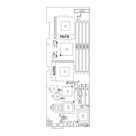
ROCKY-3742EVFG's Layout........................................................9
2.2
Clear CMOS Setup ....................................................................10
2.3
Compact Flash Card Master/Slave Mode Setting...................... 10
2.4
CPU Type Selection Setting .......................................................10
3. Connection ......................................................... 11
3.1
Floppy Disk Drive Connector......................................................11
3.2
PCI E-IDE Disk Drive Connector ................................................12
3.3
Parallel Port...............................................................................13
3.4
USB Port Connector...................................................................14
3.5
Power Button Switch ..................................................................14
3.6
Serial Ports................................................................................15
3.7
Keyboard/Mouse Connector .......................................................15
3.8
IrDA Infrared Interface Port .......................................................16
3.9
Fan Connector ..........................................................................17
3.10 VGA Connector..........................................................................17
3.11 Audio Connectors .....................................................................18
2
Advertisement
Table of Contents

Related Manuals for ICP Electronics ROCKY-3742EVFG


Summary of Contents for ICP Electronics ROCKY-3742EVFG
-
Page 1: Table Of Contents
Power Button Switch ..............14 Trademarks ROCKY-3742EVFG is registered trademarks of ICP Electronics Serial Ports................15 Inc., IBM PC is a registered trademark of International Business Keyboard/Mouse Connector ............15 Machines Corporation. - Page 2 3.12 Compact Flash Storage Card Socket ........19 Appendix A. Watch Dog Timer....... 55 3.13 ATX Connector .................20 3.14 External Switches and Indicators ..........21 Appendix B. E Key™ Function ......57 3.15 PS-ON Connector ..............21 Appendix C. Address Mapping....... 58 3.16 LAN RJ45 Connectors ...............22 3.17 External LED Connector ............23 Appendix D.
-
Page 3: Introduction
SDRAM/VCM module. The max memory is up to 1.5GB(PC133) or 2GB(PC100). Support ECC(1-bit Error Code Correct) function • Ultra ATA/33/66/100 IDE Interface : Two PCI Enhance IDE hard The ROCKY-3742EVFG ATX/AT main board is a high- drives. The south bridge VT82c686B supports Ultra ® ATA/33/66/100 IDE interface. -
Page 4: What You Have
3742EVFG/EVF/EV is shown, and the unpacking information • Keyboard connector that you should be careful is described. The jumpers and switches setting for the ROCKY-3742EVFG/EVF/EV 's • Mouse : PS/2 Mouse Port on-board. configuration, such as CPU type selection, system clock •... -
Page 5: Clear Cmos Setup
If want to clear the CMOS Setup(for example forgot the password, you should clear the CMOS and then set the password again.), you should close the JP3 (2-3) for about 3 seconds, then open again. This will set back to normal operation mode. -
Page 6: Connection
ROCKY-3742EVFG board. 6 … 36 38 40 … 3.1 Floppy Disk Drive Connector … ROCKY-3742EVFG board is equipped with a 34-pin daisy- 5 … 35 37 39 chain driver connector cable. • CN2 : FDC CONNECTOR PIN NO. -
Page 7: Parallel Port
3.3 Parallel Port 3.4 USB Port Connector The ROCKY-3742EVFG built in two USB(Spec. 1.1) ports for This port is usually connected to a printer, The ROCKY-3742EVFG the future new I/O bus expansion. CN3 : 2 ports USB Connector includes an on-board parallel port, accessed through a 26-pin flat- cable connector CN11. -
Page 8: Serial Ports
TRANSMIT DATA (TXD) 3.8 IrDA Infrared Interface Port DATA TERMINAL READY (DTR) GROUND (GND) The ROCKY-3742EVFG built in an IrDA port which supports DATA SET READY (DSR) Serial Infrared(SIR) or Amplitude Shift Keyed IR(ASKIR) REQUEST TO SEND (RTS) interface. When you use the IrDA port, you have to set COM2... -
Page 9: Fan Connector
3.9 Fan Connector 3.11 Audio Connectors The ROCKY-3742EVFG provides CPU with cooling fan The onboard AC’97 CODEC supports several audio functions. connector and chassis fan connector. These connectors can The audio connectors are described as below. supply 12V/500mA to the cooling fan. There is a “rotation” pin CN19/CN20/CN21/CN22 Connector in fan connector. -
Page 10: Compact Flash Storage Card Socket
3.12 Compact Flash Storage Card Socket 3.13 ATX Connector The ROCKY-3742EVFG/EVF/EV offers one standard ATX power The ROCKY-3742EVFG/EVF/EV configures Compact Flash connector Storage Card in IDE Mode(Used IDE 2). • CN4 : Compact Flash Storage Card Socket pin • CN12: 20-pin Connector... -
Page 11: External Switches And Indicators
3.16 LAN RJ45 Connector There are several external switches and indicators for ROCKY-3742EVFG/EVF/EV is equipped with dual Ethernet monitoring and controlling your CPU board. All the functions Controllers (Intel 82559 10/100Mbps and NS DP83820 Gigabit). are in the CN23 connector. -
Page 12: External Led Connector
3.17 External LED Connector The LED connector includes Ethernet Link/Active LED, Ethernet speed LED. CN29 External LED Connector 6 8 10 12 BIOS Setup 4.1 Introduction 7 9 11 LED + LED - LED Function This chapter discusses the Setup program built into the BIOS. The LAN 2 Speed LED (10M) Setup program allows users to configure the system. -
Page 13: Using Setup
4.3 Using Setup 4.4 Main Menu In general, you can use the arrow keys to highlight items, press Once you enter the AwardBIOS™ CMOS Setup Utility, the Main <Enter> to select, use the PageUp and PageDown keys to change Menu will appear on the screen. The Main Menu allows you to select entries, press <F1>... - Page 14 4.4.1 Setup Items PC Health Status Use this menu to monitor your hardware. The main menu includes the following main setup categories. Recall that some systems may not include all entries. Frequency/Voltage Control Use this menu to specify your settings for frequency/voltage control. Standard CMOS Features See section 4.12 for the details.
-
Page 15: Standard Cmos Setup
Abandon all CMOS value changes and exit setup. See section 4.15 Time HH : MM : SS Set the system time for the details. Options are in its sub Press <Enter> to enter Primary Master menu menu 4.5 Standard CMOS Setup (described in Table 3) detailed options Options are in its sub... - Page 16 The IDE adapters control the hard disk drive. Use a separate sub menu to configure each hard disk drive. IDE HDD Auto- Press Enter Press Enter to auto-detect the detection this channel. Figure 2 shows the IDE primary master sub menu. detection is successful, it fills the remaining fields on this menu.
- Page 17 up sequence, keyboard operation, shadowing and security. Enabled Activates automatically when the system boots up causing a warning message to appear when anything attempts to access the boot sector or hard disk partition CMOS Setup Utility – Copyright © 1984 – 2000 Award Software table.
- Page 18 System The system will not boot and access to Setup will be Boot Up Floppy Seek denied if the correct password is not entered at the Seeks disk drives during boot up. Disabling speeds boot up. prompt. The choice: Enabled, Disabled. Setup The system will boot, but access to Setup will be denied if the correct password is not entered at the prompt.
- Page 19 The Choice: Advanced Chipset Features Enabled, Disabled. DRAM Timing By SPD [Disabled] DRAM Item Help Clock [Host CLK] _______________________ DRAM Clock SDRAM Cycle Length Menu Level Bank Interleave [Disabled] This item allows you to control the DRAM speed. Memory Hole [Disabled] The Choice: Host Clock, HCLK-33M, HCLK+33M.
-
Page 20: Integrated Peripherals
Select Enabled if your system contains a Universal Serial Bus (USB) 4.8 Integrated Peripherals controller and you have a USB keyboard. The Choice: Enabled, Disabled. CMOS Setup Utility – Copyright © 1984 – 2000 Award Software OnChip Sound Integrated Peripherals OnChip IDE Channel0 [Enabled] Item Help... - Page 21 The choice: Enabled, Disabled. IDE Prefetch Mode The onboard IDE drive interfaces supports IDE prefetching for faster drive Onboard Serial Port 1/Port 2 accesses. If you install a primary and/or secondary add-in IDE interface, set this field to Disabled if the interface does not support prefetching. Select an address and corresponding interrupt for the first and second The choice: Enabled, Disabled.
-
Page 22: Power Management Setup
The choice: EPP1.7, EPP1.9 CMOS Setup Utility – Copyright © 1984 – 2000 Award Software Power Management Setup ACPI function [Disabled] Item Help Onboard Legacy Audio Power Management [Press Enter] _______________________ PM Control by APM [Yes] Menu Level This field controls the onboard legacy audio. Video Off Option [Suspend ->... - Page 23 3. Suspend Mode: the vertical and horizontal synchronization ports When enabled and after the set time of system and write blanks to the video buffer. inactivity, all devices except the CPU will be shut off. There are four selections for Power Management, three of which have Blank Screen This option only writes blanks to the video fixed mode settings.
-
Page 24: Pnp/Pci Configuration Setup
When On of HDD & FDD, any activity from one of the listed system 4.10 PnP/PCI Configuration Setup peripheral devices wakes up the system This section describes configuring the PCI bus system. PCI, or Personal Computer Interconnect, is a system which allows I/O devices PCI Master to operate at speeds nearing the speed the CPU itself uses when communicating with its own special components. -
Page 25: Pc Health Status
4.11 PC Health Status Resource controlled by The Award Plug and Play BIOS has the capacity to automatically configure all of the boot and Plug and Play compatible devices. CMOS Setup Utility – Copyright © 1984-2000 Award Software PC Health Status However, this capability means absolutely nothing unless you are Current CPU1 Temp. -
Page 26: Defaults Menu
Auto Detect DIMM/PCI Clk [ Enabled] Item Help CPU Clock/Spread Spectrum [Default] ------------------------- Selecting “Defaults” from the main menu shows you two Menu Level options which are described below Load Fail-Safe Defaults When you press <Enter> on this item you get a confirmation dialog box with a message similar to: Load Fail-Safe Defaults (Y/N) ? N Pressing ‘Y’... -
Page 27: Exit Selecting
Pressing <Enter> on this item asks for confirmation: supervisor password : can enter and change the options of the setup menus. Save to CMOS and EXIT (Y/N)? Y user password just can only enter but do not have the right to change the options of Pressing “Y”... - Page 28 will perform hardware reset (cold boot) to bring the system back to a W_LOOP: MOV DX, TIMER_STOP known state. IN AL, DX MOV DX, TIMER_START Three I/O ports control the operation of WatchDog Timer. IN AL, DX ;;Restart counter ;;Add Your Appliaction Here 443 (hex) Write Set WatchDog Time period...
-
Page 29: Appendix B. E Key™ Function
To easily start to use the function, please refer to the included Appendix B. E Key™ Function EKEYDEMO.C code at first. The ROCKY-3742EVFG provides an outstanding E KEY™ function for system integrator. Based on the E KEY™, you can free to store the ID Code, Password or Critical Data in the 1Kbit EEPROM. -
Page 30: Appendix C. Address Mapping
Appendix C. Address Mapping 1st MB Memory Address Map Memory address Description 00000-9FFFF System memory A0000-BFFFF VGA buffer IO Address Map C0000-C7FFF VGA BIOS F0000-FFFFF System BIOS I/O address Range Description 1000000- Extend BIOS 000-01F DMA Controller #1 *Default setting 020-021 Interrupt Controller #1, Master 040-05F... -
Page 31: Appendix D. Atx Power Supply
ATX power supply through backplane’s PS ON 2.1. ROCKY-3742EVFG (through Power Button & GND): connector. Refer to the figure below: for the backplanes with ATX connector, the connection can be made simply as following:... - Page 32 The ROCKY-3742EVFG provides two kind of Wake Up Function. This page describes how to use Modem Wake-Up and LAN Wake-Up function. Wake-Up function is working while you use ATX power supply, Wake-Up By Modem Ring On: You must set the option Wake Up On LAN/Ring of CMOS SETUP to be enabled.
Need help?
Do you have a question about the ROCKY-3742EVFG and is the answer not in the manual?
Questions and answers