Vega VEGASON 62 Operating Instructions Manual
Ultrasonic sensor for continuous level measurement
Hide thumbs
Also See for VEGASON 62:
- Operating instructions manual (68 pages) ,
- Quick setup manual (24 pages) ,
- Operating instructions manual (64 pages)

Related Manuals for Vega VEGASON 62


Summary of Contents for Vega VEGASON 62
- Page 1 Operating Instructions Ultrasonic sensor for continuous level measurement VEGASON 62 Foundation Fieldbus Document ID: 28791...
-
Page 2: Table Of Contents
Save parameter adjustment data..................46 Set up with other systems ....................47 DD adjustment programs ....................47 9 Maintenance and fault rectification ..................48 9.1 Maintenance ........................48 9.2 Rectify faults ........................48 Exchanging the electronics module ................49 Software update ......................50 VEGASON 62 • Foundation Fieldbus... - Page 3 11.4 Industrial property rights ....................64 11.5 Trademark ........................64 Safety instructions for Ex areas: Take note of the Ex specific safety instructions for Ex applications. These instructions are attached as documents to each instrument with Ex approval and are part of the operating instructions. Editing status: 2023-10-24 VEGASON 62 • Foundation Fieldbus...
-
Page 4: About This Document
Symbols used Document ID This symbol on the front page of this instruction refers to the Docu- ment ID. By entering the Document ID on www.vega.com you will reach the document download. Information, note, tip: This symbol indicates helpful additional infor- mation and tips for successful work. -
Page 5: For Your Safety
During work on and with the device, the required personal protective equipment must always be worn. Appropriate use VEGASON 62 is a sensor for continuous level measurement. You can find detailed information about the area of application in chapter "Product description". Operational reliability is ensured only if the instrument is properly used according to the specifications in the operating instructions manual as well as possible supplementary instructions. -
Page 6: Fulfillment Of Namur Recommendations
That is why we have introduced an environment management system with the goal of continuously improving company environmental pro- tection. The environment management system is certified according to DIN EN ISO 14001. Please help us fulfil this obligation by observing the environmental instructions in this manual: • Chapter "Packaging, transport and storage" • Chapter "Disposal" VEGASON 62 • Foundation Fieldbus... -
Page 7: Product Description
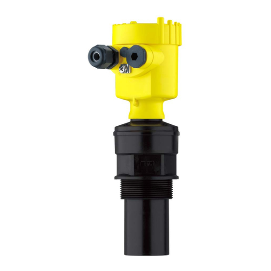
Housing with electronics, optionally available with plug connector • Housing cover, optionally available with display and adjustment module PLICSCOM The components are available in different versions. Fig. 1: VEGASON 62, threaded version with plastic housing Housing cover with integrated PLICSCOM (optional) Housing with electronics 3 Process fitting with transducer The type label contains the most important data for identification and... -
Page 8: Principle Of Operation
Move to "www.vega.com" and enter in the search field the serial number of your instrument. • Scan the QR code on the type label. • Open the VEGA Tools app and enter the serial number under "Documentation". Principle of operation Application area VEGASON 62 is an ultrasonic sensor for continuous level measure- ment. It is suitable for liquids and solids in virtually all industries, particularly in the water and waste water industry. -
Page 9: Packaging, Transport And Storage
The display and adjustment module is used for measured value indi- Display and adjustment module cation, adjustment and diagnosis. The integrated Bluetooth module (optional) enables wireless adjust- ment via standard adjustment devices. VEGACONNECT The interface adapter VEGACONNECT enables the connection of communication-capable instruments to the USB interface of a PC. VEGASON 62 • Foundation Fieldbus... - Page 10 3 Product description The VEGADIS 81 is an external display and adjustment unit for VEGA VEGADIS 81 plics sensors. ® Protective cover The protective cover protects the sensor housing against soiling and intense heat from solar radiation. Flanges Screwed flanges are available in different versions according to the following standards: DIN 2501, EN 1092-1, BS 10, ASME B 16.5, JIS B 2210-1984, GOST 12821-80.
-
Page 11: Mounting
(e.g. through cleaning processes) or on cooled or heated vessels. To maintain the housing protection, make sure that the housing lid is closed during operation and locked, if necessary. VEGASON 62 • Foundation Fieldbus... -
Page 12: Housing Features
This influences the measuring result, particularly if the level is very low. With pressures under -0.2 bar (-20 kPa) you should use a different measuring principle, e.g. radar or guided radar (TDR). Housing features Filter element The filter element in the housing is used for ventilation of the housing. For effective ventilation, the filter element must always be free of deposits. Therefore, mount the device so that the filter element is protected against deposits. Note: Do not use a high-pressure cleaner to clean housings in standard types of protection. The filter element could be damaged and mois- ture could penetrate the housing. VEGASON 62 • Foundation Fieldbus... - Page 13 Housing orientation The housing of VEGASON 62 can be rotated completely by 360°. This enables optimal reading of the display and easy cable entry. For housings made of plastic or electropolished stainless steel, this is done without tools.
- Page 14 3. Check if the cover can no longer be turned The housing cover is unlocked in the opposite way. Note: The locking screw has two holes drilled through the head. Thus it can also be sealed. VEGASON 62 • Foundation Fieldbus...
-
Page 15: Mounting Instructions
4 Mounting Mounting instructions Screwing in Screw VEGASON 62 into the mounting socket with an appropriate spanner applied to the hexagon of the process fitting. Max. torque see chapter "Technical data". Warning: The housing must not be used to screw the instrument in! Applying tightening force can damage internal parts of the housing. - Page 16 10 mm (0.394 in) out of the nozzle. Fig. 8: Recommended socket mounting If the reflective properties of the medium are good, you can mount VEGASON 62 on sockets which are higher than the length of the transducer. You will find recommended values for socket heights in the following illustration. The socket end should be smooth and burr-free, if possible also rounded.
- Page 17 "clear view" to the measured product. In case of existing vessel installations, a false signal suppression should be carried out during setup. VEGASON 62 • Foundation Fieldbus...
- Page 18 α Fig. 12: Cover flat, large-area profiles with deflectors Agitators If there are agitators in the vessel, a false signal suppression should be carried out with the agitators in motion. This ensures that the interfering reflections from the agitators are saved with the blades in different positions. Fig. 13: Agitators Do not mount the instruments in or above the filling stream. Make sure Inflowing medium that you detect the medium surface, not the inflowing product. VEGASON 62 • Foundation Fieldbus...
- Page 19 Standpipe measurement By using a standpipe (surge or bypass tube), the influence of vessel installations, foam generation and turbulence is excluded. Standpipes must extend all the way down to the requested min. level, as measurement is only possible within the tube. VEGASON 62 • Foundation Fieldbus...
- Page 20 Fig. 15: Standpipe in the tank Vent hole: ø 5 … 10 mm (0.197 … 0.394 in) VEGASON 62 can be used from tube diameters of 50 mm (1.969 in). Avoid large gaps and thick welding joints when connecting the tubes.
- Page 21 In general, the following points must be observed: • Installation of the sensor at the inlet side • Installation in the centre of the flume and vertical to the liquid surface • Distance to the Venturi flume • Distance of the sensor to the max. height of damming by taking the blocking distance into account VEGASON 62 • Foundation Fieldbus...
-
Page 22: Connecting To Power Supply
Prior to setup you have to replace these protective caps with ap- proved cable glands or close the openings with suitable blind plugs. On plastic housings, the NPT cable gland or the Conduit steel tube must be screwed into the threaded insert without grease. Max. torque for all housings, see chapter "Technical data". VEGASON 62 • Foundation Fieldbus... -
Page 23: Connection Procedure
5. Insert the cable into the sensor through the cable entry 6. Lift the opening levers of the terminals with a screwdriver (see following illustration) 7. Insert the wire ends into the open terminals according to the wir- ing plan VEGASON 62 • Foundation Fieldbus... -
Page 24: Wiring Plan, Single Chamber Housing
Fig. 19: Material versions, single chamber housing Plastic Aluminium Stainless steel (precision casting) Stainless steel (electro-polished) Filter element for air pressure compensation of all material versions. Blind plug with version IP66/IP68 (1 bar) for Aluminium and stainless steel VEGASON 62 • Foundation Fieldbus... -
Page 25: Wiring Plan, Double Chamber Housing
Display I 2 C Fig. 21: Wiring plan - single chamber housing Voltage supply, signal output Wiring plan, double chamber housing The following illustrations apply to the non-Ex as well as to the Ex-ia version. VEGASON 62 • Foundation Fieldbus... - Page 26 Fig. 23: Electronics compartment - double chamber housing Simulation switch ("on" = simulation mode) Spring contacts for display and adjustment module Interface for service Internal connection cable to the connection compartment Ground terminal for connection of the cable screening VEGASON 62 • Foundation Fieldbus...
-
Page 27: Wiring Plan - Version Ip66/Ip68 (1 Bar)
Brown (+) and blue (-) to power supply or to the processing system Shielding Switch-on phase Switch-on phase After VEGASON 62 is connected to voltage supply or after voltage recurrence, the instrument carries out a self-check for approx. 30 seconds. The following steps are carried out: •... - Page 28 Then the current measured value will be displayed and the corre- sponding digital output signal will be output to the cable. The values correspond to the actual measured level as well as to the settings already carried out, e.g. default setting. VEGASON 62 • Foundation Fieldbus...
-
Page 29: Set Up With The Display And Adjustment Module Plicscom
The display and adjustment module is powered by the sensor, an ad- ditional connection is not necessary. Fig. 27: Insert display and adjustment module in the single chamber housing Note: If you intend to retrofit the instrument with a display and adjustment module for continuous measured value indication, a higher lid with an inspection glass is required. VEGASON 62 • Foundation Fieldbus... -
Page 30: Adjustment System
5 s, the display returns to the main menu. The menu language is then switched over to "English". Approx. 60 minutes after the last pressing of a key, an automatic reset to measured value indication is triggered. Any values not confirmed with [OK] will not be saved. VEGASON 62 • Foundation Fieldbus... -
Page 31: Setup Steps
Basic adjustment - Min. Proceed as follows: adjustment 1. Move from the measured value display to the main menu by pushing [OK]. Basic adjustment Display Diagnostics Service Info 2. Select the menu item "Basic adjustment" with [->] and confirm with [OK]. Now the menu item "Min. adjustment" is displayed. VEGASON 62 • Foundation Fieldbus... - Page 32 "Solid". Medium Liquid With solids, you can also choose between "Powder/Dust", "Granular/ Pellets" or "Ballast/Pebbels". Through this additional selection, the sensor is adapted perfectly to the product and measurement reliability, particularly in products with poor reflective properties, is considerably increased. VEGASON 62 • Foundation Fieldbus...
- Page 33 "Display". Linearisation curve Linear Enter the requested parameters via the appropriate keys, save your settings and jump to the next menu item with the [->] key. VEGASON 62 • Foundation Fieldbus...
- Page 34 > 10 dB. Diagnostics - Device The instrument status is displayed in this menu item. If no failure is status detected by the sensor, "OK" will be displayed. If a failure is detected, VEGASON 62 • Foundation Fieldbus...
- Page 35 The following functions are available with "Echo and false echo curve": • "X-Zoom": Zoom function for the meas. distance • "Y-Zoom": 1, 2, 5 and 10x signal magnification in "dB" • "Unzoom": Reset the presentation to the nominal measuring range without magnification In the menu item "Trend curve" the following are available: • "X-Zoom": Resolution – 1 minute – 1 hour VEGASON 62 • Foundation Fieldbus...
- Page 36 Service - Extended set- The menu item "Extended setting" offers the possibility to optimise ting VEGASON 62 for applications in which the level changes very quickly. To do this, select the function "Quick level change > 1 m/min.". Extended setting quick level change > 1 m/min.
- Page 37 If the "Reset" is carried out, the sensor resets the values of the follow- ing menu items to the reset values (see table): Function Reset value Max. adjustment Final value dead zone in m(d) Sensor-specific basic adjustment. Depending on the sensor type, see chapter "Technical data". VEGASON 62 • Foundation Fieldbus...
- Page 38 Deutsch • English • Français • Espanõl • Pycckuu • Italiano • Netherlands • Japanese • Chinese Depending on the sensor type, see chapter "Technical data". Special parameters are parameters which are set customer-specifically on the service level with the adjustment software PACTware. VEGASON 62 • Foundation Fieldbus...
- Page 39 Activate permanently? Only the following functions are permitted with activated PIN: • Select menu items and show data • Read data from the sensor into the display and adjustment module Menu section, info Info In this menu item the most important sensor information can be displayed: VEGASON 62 • Foundation Fieldbus...
-
Page 40: Menu Schematic
< max. 32 characters > • Sensor details, e.g. approval, process fitting, seal, measuring cell, measuring range, electronics, housing, cable entry, plug, cable length etc. Sensor characteristics Display now? Menu schematic Information: Depending on the version and application, the highlighted menu windows may not always be available. VEGASON 62 • Foundation Fieldbus... - Page 41 Diagnostics Service Info Peak indicator Measurement reliability Curve selection Echo curve Distance min.: 0.580 m(d) 36 dB Dist. max.: 16.785 m(d) Device status Echo curve Presentation of the echo curve T-max.: 30.6 °C T-min.: 4.5 °C VEGASON 62 • Foundation Fieldbus...
-
Page 42: Saving The Parameterisation Data
In the display and adjust- If the instrument is equipped with a display and adjustment module, ment module the parameter adjustment data can be saved in it. The data remain VEGASON 62 • Foundation Fieldbus... - Page 43 6 Set up with the display and adjustment module PLICSCOM permanently stored there even if the sensor supply fails. The proce- dure is described in menu item "Copy sensor data". VEGASON 62 • Foundation Fieldbus...
-
Page 44: Setup With Pactware
Interface adapter VEGACONNECT Sensor Via interface adapter external TWIST Fig. 31: Connection via interface adapter VEGACONNECT external I²C bus (com.) interface on the sensor I²C connection cable of VEGACONNECT Interface adapter VEGACONNECT USB cable to the PC VEGASON 62 • Foundation Fieldbus... -
Page 45: Parameter Adjustment
A description of the update procedure is also available in the Internet. Further setup steps are described in the operating instructions manu- al "DTM Collection/PACTware" attached to each DTM Collection and which can also be downloaded from the Internet. Detailed descrip- tions are available in the online help of PACTware and the DTMs. VEGASON 62 • Foundation Fieldbus... -
Page 46: Save Parameter Adjustment Data
7 Setup with PACTware Fig. 33: Example of a DTM view Save parameter adjustment data We recommend documenting or saving the parameterisation data via PACTware. That way the data are available for multiple use or service purposes. VEGASON 62 • Foundation Fieldbus... -
Page 47: Set Up With Other Systems
8 Set up with other systems Set up with other systems DD adjustment programs Device descriptions as Enhanced Device Description (EDD) are available for DD adjustment programs such as, for example, AMS™ and PDM. The files can be downloaded at www.vega.com/downloads under "Software". VEGASON 62 • Foundation Fieldbus... -
Page 48: Maintenance And Fault Rectification
Measured value on the The menu item "Display - Check values and correct, if necessary display and adjustment Display value" is not set to module does not corre- "AI-Out" spond to the value in the VEGASON 62 • Foundation Fieldbus... -
Page 49: Exchanging The Electronics Module
Should these measures not be successful, please call in urgent cases 24 hour service hotline the VEGA service hotline under the phone no. +49 1805 858550. The hotline is also available outside normal working hours, seven days a week around the clock. -
Page 50: Software Update
Details of the medium Print the generated instrument return form. Clean the instrument and pack it damage-proof. Send the printed instrument return form and possibly a safety data sheet together with the device. You will find the address for the return on the generated instrument return form. VEGASON 62 • Foundation Fieldbus... -
Page 51: Dismount
If personal data is stored on the old device to be disposed of, delete it before disposal. If you have no way to dispose of the old instrument properly, please contact us concerning return and disposal. VEGASON 62 • Foundation Fieldbus... -
Page 52: Supplement
Foundation Fieldbus protocol Ʋ Physical layer according to IEC 61158-2 Cycle time min. 1 s (dependent on the parameter setting) Ʋ Damping (63 % of the input variable) 0 … 999 s, adjustable Glass (with Aluminium and stainless steel precision casting housing) VEGASON 62 • Foundation Fieldbus... - Page 53 (13.123 ft) (16.404 ft) (19.685 ft) (22.966 ft) (26.247 ft) (3.28 ft) (6.562 ft) -10 mm (-0.394 in) -16 mm (-0.63 in) Fig. 34: Deviation VEGASON 62 Reference conditions to measurement accuracy (according to DIN EN 60770-1) Reference conditions according to DIN EN 61298-1 Ʋ Temperature +18 … +30 °C (+64 … +86 °F) Ʋ Relative humidity 45 … 75 % Ʋ Air pressure 860 … 1060 mbar/86 … 106 kPa (12.5 … 15.4 psig) Other reference conditions Ʋ...
- Page 54 Ʋ Min. bending radius 25 mm (0.984 in) with 25 °C (77 °F) Ʋ Diameter approx. 8 mm (0.315 in) Ʋ Colour - Non-Ex version Black Relating to the nominal measuring range. Tested according to the guidelines of German Lloyd, GL directive 2. VEGASON 62 • Foundation Fieldbus...
- Page 55 Single chamber IP66/IP68 (0.2 bar) Type 6P polished) Stainless steel (precision Single chamber IP66/IP68 (0.2 bar) Type 6P casting) IP68 (1 bar) Type 6P Connection of the feeding power supply Networks of overvoltage category III unit VEGASON 62 • Foundation Fieldbus...
-
Page 56: Device Communication Foundation Fieldbus
For that reason the associated approval documents of these instruments have to be carefully noted. They are part of the delivery or can be downloaded by entering the serial number of your instrument into the search field under www.vega.com as well as in the general download area. 11.2 Device communication Foundation Fieldbus In the following, the necessary device-specific details are shown. You can find further information of... - Page 57 C! a nnel ! ! ! Secondary Value 2 AI ! C! a nnel ! ! ! Tem! e rature Fig. 35: VEGASON 62 measured value processing Diagram, adjustment The following illustration shows the function of the adjustment: Secondary_value_1 cal_level_hi...
- Page 58 SUB_DEVICE_NUMBER • SENSOR_ELEMENT_TYPE • display_source_selector – Selects the type of value, which is displayed on the indicating and adjustment module • max_peak_sensor_value – Holds the maximum sensor value. Write access resets to current value. Unit derives from 'Sen- sor_range.unit' • min_peak_sensor_value – Holds the minimum sensor value. Write access resets to current value. Unit derives from 'Sen- sor_range.unit' • CAL_POINT_HI – Min./max.-adjustment: Upper calibrated point of the sensor. It refers to 'Cal_level_hi'. The unit is defined in 'Sensor_range.unit'hi VEGASON 62 • Foundation Fieldbus...
- Page 59 • first_echo_factor – Set up to suit the process conditions • pulse_velocity_correction – Set up to suit the process conditions • echo_quality – Signal/Noise ratio • empty_vessel_curve_corr_dist – Distance from the sensor to the product surface. Unit derives from 'Sensor_range.unit' • empty_vessel_curve_corr_op_code VEGASON 62 • Foundation Fieldbus...
-
Page 60: Dimensions
(3.11") (3.11") M16x1,5 M20x1,5/ ½ NPT M20x1,5/ ½ NPT Fig. 37: Housing versions in protection IP66/IP67 (with integrated display and adjustment module the housing is 9 mm/0.35 in higher) Plastic single chamber Plastic double chamber VEGASON 62 • Foundation Fieldbus... - Page 61 M20x1,5 M20x1,5/ ½ NPT Fig. 39: Housing version with protection rating IP66/IP68 (1 bar), (with integrated display and adjustment module the housing is 18 mm/0.71 in higher) Aluminium - single chamber Aluminium - double chamber VEGASON 62 • Foundation Fieldbus...
- Page 62 ø 84 mm (3.31") M20x1,5 M20x1,5 Fig. 41: Housing version with protection rating IP66/IP68 (1 bar), (with integrated display and adjustment module the housing is 18 mm/0.71 in higher) Stainless steel single chamber (precision casting) VEGASON 62 • Foundation Fieldbus...
- Page 63 2"NPT ø 50mm ") ø 74mm ") Fig. 42: VEGASON 62 Blocking distance: 0.4 m (1.312 ft) Measuring range: with liquids up to 8 m (26.25 ft), with solids up to 3.5 m (11.48 ft) VEGASON 62 • Foundation Fieldbus...
-
Page 64: Industrial Property Rights
Les lignes de produits VEGA sont globalement protégées par des droits de propriété intellec- tuelle. Pour plus d'informations, on pourra se référer au site www.vega.com. VEGA lineas de productos están protegidas por los derechos en el campo de la propiedad indus- trial. Para mayor información revise la pagina web www.vega.com. - Page 65 Notes VEGASON 62 • Foundation Fieldbus...
- Page 66 Notes VEGASON 62 • Foundation Fieldbus...
- Page 67 Notes VEGASON 62 • Foundation Fieldbus...
- Page 68 Subject to change without prior notice © VEGA Grieshaber KG, Schiltach/Germany 2023 VEGA Grieshaber KG Am Hohenstein 113 Phone +49 7836 50-0 77761 Schiltach E-mail: info.de@vega.com...
Need help?
Do you have a question about the VEGASON 62 and is the answer not in the manual?
Questions and answers