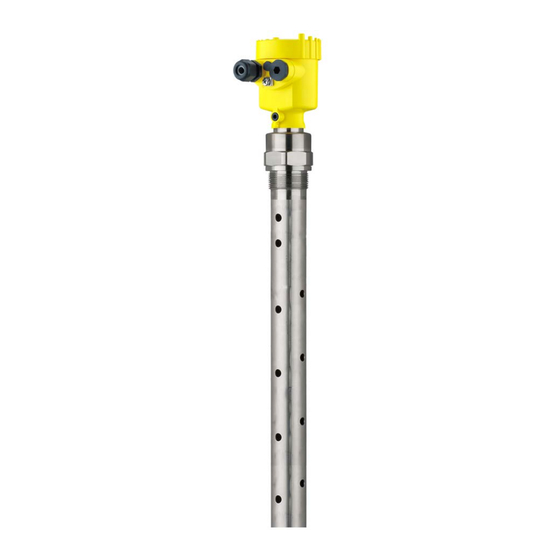
Vega VEGAFLEX 81 Operating Instructions Manual
Tdr sensor for continuous level and interface measurement of liquids
Hide thumbs
Also See for VEGAFLEX 81:
- Operating instructions manual (100 pages) ,
- Quick setup manual (24 pages) ,
- Mounting instructions (20 pages)

Related Manuals for Vega VEGAFLEX 81


Summary of Contents for Vega VEGAFLEX 81
- Page 1 Operating Instructions TDR sensor for continuous level and interface measurement of liquids VEGAFLEX 81 Profibus PA Coax probe Document ID: 44214...
-
Page 2: Table Of Contents
Connecting ........................47 Sensor parameter adjustment ..................48 Setup with PACTware ......................49 Connect the PC ......................49 Parameter adjustment ....................49 Set up with the quick setup ..................... 50 Save parameter adjustment data..................52 VEGAFLEX 81 • Profibus PA... - Page 3 11.2 Disposal ......................... 63 12 Supplement ..........................64 12.1 Technical data ........................ 64 12.2 Device communication Profibus PA ................73 12.3 Dimensions ........................77 12.4 Industrial property rights ....................81 12.5 Trademark ........................81 Editing status: 2023-12-04 VEGAFLEX 81 • Profibus PA...
-
Page 4: About This Document
Symbols used Document ID This symbol on the front page of this instruction refers to the Docu- ment ID. By entering the Document ID on www.vega.com you will reach the document download. Information, note, tip: This symbol indicates helpful additional infor- mation and tips for successful work. -
Page 5: For Your Safety
During work on and with the device, the required personal protective equipment must always be worn. Appropriate use VEGAFLEX 81 is a sensor for continuous level measurement. You can find detailed information about the area of application in chapter "Product description". -
Page 6: Namur Recommendations
The environment management system is certified according to DIN EN ISO 14001. Please help us fulfil this obligation by observing the environmental instructions in this manual: • Chapter "Packaging, transport and storage" VEGAFLEX 81 • Profibus PA... - Page 7 2 For your safety • Chapter "Disposal" VEGAFLEX 81 • Profibus PA...
-
Page 8: Product Description
"Documentation". Principle of operation Application area The VEGAFLEX 81 is a level sensor with coax probe for continuous level or interface measurement, suitable for applications in liquids. Functional principle - High frequency microwave pulses are guided along a steel cable or level measurement a rod. - Page 9 Fig. 2: Interface measurement 1 Sensor reference plane (seal surface of the process fitting) d1 Distance to the interface d2 Distance to the level TS Thickness of the upper medium (d1 - d2) h1 Height - Interface h2 Height - Level L1 Lower medium L2 Upper medium L3 Gas phase VEGAFLEX 81 • Profibus PA...
-
Page 10: Packaging, Transport And Storage
Ascertained transit damage or con- cealed defects must be appropriately dealt with. Storage Up to the time of installation, the packages must be left closed and stored according to the orientation and storage markings on the outside. VEGAFLEX 81 • Profibus PA... -
Page 11: Accessories
VEGACONNECT The interface adapter VEGACONNECT enables the connection of communication-capable instruments to the USB interface of a PC. VEGADIS 81 The VEGADIS 81 is an external display and adjustment unit for VEGA plics sensors. ® VEGADIS adapter The VEGADIS adapter is an accessory part for sensors with double chamber housing. -
Page 12: Mounting
For safety reasons, the instrument must only be operated within the permissible process conditions. You can find detailed information on the process conditions in chapter "Technical data" of the operating instructions or on the type label. VEGAFLEX 81 • Profibus PA... -
Page 13: Mounting Instructions
By doing this, you avoid damage to the electronics through inductive coupling. Inflowing medium Do not mount the instruments in or above the filling stream. Make sure that you detect the medium surface, not the inflowing product. VEGAFLEX 81 • Profibus PA... - Page 14 In case of strong external vibrations or if there is a danger of the co- axial probe touching the vessel wall, then the probe must be fastened at the bottom end. Keep in mind that measurement is not possible below the fastening point. VEGAFLEX 81 • Profibus PA...
- Page 15 4 Mounting Fig. 5: Fasten the probe Coax probe Retaining sleeve VEGAFLEX 81 • Profibus PA...
-
Page 16: Connecting To Power Supply
Note: Prior to setup you have to replace these protective caps with ap- proved cable glands or close the openings with suitable blind plugs. VEGAFLEX 81 • Profibus PA... -
Page 17: Connecting
5. Insert the cable into the sensor through the cable entry Fig. 6: Connection steps 5 and 6 Single chamber housing Double chamber housing 6. Insert the wire ends into the terminals according to the wiring plan VEGAFLEX 81 • Profibus PA... -
Page 18: Wiring Plan - Single Chamber Housing
Selection switch for instrument address For external display and adjustment unit Ground terminal for connection of the cable screening Wiring plan - double chamber housing The following illustration applies to the non-Ex, Ex ia and Ex d version. VEGAFLEX 81 • Profibus PA... - Page 19 6 7 8 Fig. 9: Connection compartment - double chamber housing Voltage supply, signal output For display and adjustment module or interface adapter For external display and adjustment unit Ground terminal for connection of the cable screening VEGAFLEX 81 • Profibus PA...
-
Page 20: Double Chamber Housing With Vegadis-Adapter
Fig. 11: Top view of the M12 x 1 plug connector Pin 1 Pin 2 Pin 3 Pin 4 Contact pin Colour, connection ca- Terminal, electronics ble in the sensor module Pin 1 Brown Pin 2 White Pin 3 Blue Pin 4 Black VEGAFLEX 81 • Profibus PA... -
Page 21: Wiring Plan - Version Ip66/Ip68 (1 Bar)
The hardware addressing is effective if an address <126 is set with the address selection switches on the instrument. Software address- ing is then no longer effective, the set hardware address applies. 6 7 8 Fig. 13: Address selection switch 1 Addresses <100 (selection 0), addresses >100 (selection 1) 2 Decade of the address (selection 0 to 9) 3 Unit position of the address (selection 0 to 9) VEGAFLEX 81 • Profibus PA... -
Page 22: Switch-On Phase
The addressing procedure is described in the operating instructions manual "Display and adjustment module. Switch-on phase After connecting VEGAFLEX 81 to the bus system, the device first performs a self-test: • Internal check of the electronics •... -
Page 23: Set Up With The Display And Adjustment Module
The display and adjustment module is powered by the sensor, an ad- ditional connection is not necessary. Fig. 14: Installing the display and adjustment module in the electronics compart- ment of the single chamber housing VEGAFLEX 81 • Profibus PA... -
Page 24: Adjustment System
– Confirm selected menu – Edit parameter – Save value • [->] key: – Change measured value presentation – Select list entry – Select editing position • [+] key: – Change value of the parameter VEGAFLEX 81 • Profibus PA... - Page 25 Any values not confirmed with [OK] will not be saved. Switch-on phase After switching on, the VEGAFLEX 81 carries out a short self-test where the device software is checked. The output signal transmits a fault signal during the switch-on phase.
-
Page 26: Parameter Adjustment - Quick Setup
"Parameter adjustment - Extended adjustment". Parameter adjustment - Extended adjustment For technically demanding measuring points, you can carry out extended settings in "Extended adjustment". The main menu is divided into five sections with the following func- Main menu tions: VEGAFLEX 81 • Profibus PA... - Page 27 Hardware addressing is effective if an address less than 126 is set with the address selection switches on the electronics module of VEGAFLEX 81. In such case, software addressing has no effect - only the set hardware address applies. Software addressing Software addressing is only effective if address 126 or higher is set on the instrument with the address selection switches.
- Page 28 When choosing "No", you can enter the probe length manually. Application - Medium Coax probes can be only used in liquids. In this menu item, the fixed type adjusted medium type "Liquid" is displayed. VEGAFLEX 81 • Profibus PA...
- Page 29 "Application". In this menu item you can enter if there is a superimposed gas phase in your application. Only set the function to "Yes", if the gas phase is permanently pre- sent. VEGAFLEX 81 • Profibus PA...
- Page 30 Min. adjustment - Level In this menu item you can enter the min. adjustment for the level. With interface measurement this is the minimum total level. Adjust the requested percentage value with [+] and store with [OK]. VEGAFLEX 81 • Profibus PA...
- Page 31 Enter the respective distance value in m for the interface correspond- ing to the percentage value of the interface. False signal suppression The following circumstances cause interfering reflections and can influence the measurement: • High mounting nozzles • Vessel internals such as struts VEGAFLEX 81 • Profibus PA...
- Page 32 Corresponding linearisation curves are preprogrammed for these vessels. They represent the correlation between the level percentage and vessel volume. VEGAFLEX 81 • Profibus PA...
- Page 33 If the nozzle is lower than the up- per edge of the vessel, this value can also be negative. Fig. 18: Vessel height and socket correction value D Vessel height +h Positive socket correction value -h Negative socket correction value VEGAFLEX 81 • Profibus PA...
- Page 34 To damp process-dependent measured value fluctuations, you can set a time of 0 … 999 s in this menu item. The damping applies to the level and interface measurement. The default setting is a damping of 0 s. VEGAFLEX 81 • Profibus PA...
- Page 35 In this menu item, you define the indication of the measured value on the display. You can display two different measured values. In this menu item, you define measured value 1. The default setting for the displayed value 1 is "Filling height Level". VEGAFLEX 81 • Profibus PA...
- Page 36 The two values are displayed in the menu item "Peak indicator, distance". If you have selected interface measurement under the menu item "Setup - Application", the peak values of the interface measurement are displayed in addition to the peak values of the level measurement. VEGAFLEX 81 • Profibus PA...
- Page 37 The values are displayed in the menu item "Peak indicator Additional". This menu item displays the peak values of the electronics tempera- ture as well as the dielectric constant. In another window you can carry out a reset of the two peak values separately. VEGAFLEX 81 • Profibus PA...
- Page 38 With this, you can detect signal changes over the operating time. With the adjustment software PACTware and the PC, the high-resolution echo curve can be displayed and used to compare the echo curve of the setup with the actual echo curve. VEGAFLEX 81 • Profibus PA...
- Page 39 Any stored false signal suppression or user-programmed linearisation curve, as well as the measured value memory, are deleted. Basic settings: Resetting of the parameter settings incl. special parameters to the default values (presettings) of the respective instru- VEGAFLEX 81 • Profibus PA...
- Page 40 AI FB1 Tag Descriptor AI FB1 Channel Primary Value (lin. percent level) AI FB1 scaling PV Scale (min.) AI FB1 scaling PV Scale (max.) 100 % AI FB1 Lin. Type Linear AI FB1 Out Scale Unit VEGAFLEX 81 • Profibus PA...
- Page 41 Device memory - Measured value memory - Start with meas- Not active ured value Device memory - Measured value memory - Stop with meas- Not active ured value Device memory - Measured value memory - Stop recording Not active when memory is full VEGAFLEX 81 • Profibus PA...
- Page 42 AI FB3 Out Scale (min.) AI FB3 Out Scale (max.) 100 % AI FB3 PV FTime AI FB3 Hi Hi Limit 3.402823E+38 % AI FB3 Hi Limit 3.402823E+38 % AI FB3 Lo Lo Limit -3.402823E+38 % VEGAFLEX 81 • Profibus PA...
- Page 43 TAG number this sensor had. Tip: We recommend to save the instrument adjustments. In case of an electronics exchange the saved parameter adjustment data relieve this process. VEGAFLEX 81 • Profibus PA...
- Page 44 In this menu item, the Profibus ident number of your sensor is dis- played. Sensor characteristics In this menu item, the features of the sensor such as approval, pro- cess fitting, seal, measuring range, electronics, housing and others are displayed. Example for displayed sensor features. VEGAFLEX 81 • Profibus PA...
-
Page 45: Save Parameter Adjustment Data
In the display and adjust- If the instrument is equipped with a display and adjustment module, ment module the parameter adjustment data can be saved therein. The procedure is described in menu item "Copy device settings". VEGAFLEX 81 • Profibus PA... -
Page 46: Set Up With Smartphone/Tablet/Pc/Notebook Via Bluetooth
The default setting of the sensor PIN is "0000". First of all you have to change the sensor PIN in the adjustment menu of the respective sensor, e.g. to "1111". Use "OK" to switch to the input menu. Basic adjustment Display Diagnostics Service Info Deactivate permanently? VEGAFLEX 81 • Profibus PA... -
Page 47: Connecting
Bluetooth-capable instru- ments in the area. PC/Notebook Start PACTware and the VEGA project assistant. Select the device search via Bluetooth and start the search function. The device auto- matically searches for Bluetooth-capable devices in the vicinity. -
Page 48: Sensor Parameter Adjustment
Sensor parameter adjustment The sensor parameterization is carried out via the adjustment app on the smartphone/tablet or the DTM on the PC/notebook. App view Fig. 20: Example of an app view - Setup sensor adjustment VEGAFLEX 81 • Profibus PA... -
Page 49: Setup With Pactware
Further setup steps are described in the operating instructions manu- al "DTM Collection/PACTware" attached to each DTM Collection and which can also be downloaded from the Internet. Detailed descrip- tions are available in the online help of PACTware and the DTMs. VEGAFLEX 81 • Profibus PA... -
Page 50: Set Up With The Quick Setup
The quick setup is another option for parameter adjustment of the sensor. It allows fast, convenient adjustment of the most important parameters to adapt the sensor quickly to standard applications. To use it, select the function "Quick setup" in the start screen. VEGAFLEX 81 • Profibus PA... - Page 51 Extended adjustment Maintenance Quick setup With quick setup you can carry out the parameter adjustment of VEGAFLEX 81 for your application in just a few simple steps. The assistant-driven adjustment includes the basic settings for simple, reliable setup and commissioning. Information: If the function is inactive, then possibly no instrument is connected.
-
Page 52: Save Parameter Adjustment Data
8 Setup with PACTware Save parameter adjustment data We recommend documenting or saving the parameterisation data via PACTware. That way the data are available for multiple use or service purposes. VEGAFLEX 81 • Profibus PA... -
Page 53: Set Up With Other Systems
Set up with other systems DD adjustment programs Device descriptions as Enhanced Device Description (EDD) are available for DD adjustment programs such as, for example, AMS™ and PDM. The files can be downloaded at www.vega.com/downloads under "Software". VEGAFLEX 81 • Profibus PA... -
Page 54: Diagnosis, Asset Management And Service
• Switch-on and switch-off times • Status messages (according to NE 107) • Error messages (according to NE 107) The data are read out via a PC with PACTware/DTM or the control system with EDD. VEGAFLEX 81 • Profibus PA... -
Page 55: Asset Management Function
This status message is always active. It cannot be deactivated by the user. Function check: The instrument is being worked on, the measured value is temporarily invalid (for example during simulation). This status message is inactive by default. VEGAFLEX 81 • Profibus PA... - Page 56 Duration up to approx. 3 minutes depending on the version and pa- rameter settings F113 Error in the internal instrument com- Disconnect operating voltage briefly munication Communication Send instrument for repair error VEGAFLEX 81 • Profibus PA...
- Page 57 Code Cause Rectification Text message Diagnostics S600 Temperature of the processing elec- Check ambient temperature Bit 23 tronics in the non-specified section Impermissible Insulate electronics electronics tem- Use instrument with higher temper- perature ature range VEGAFLEX 81 • Profibus PA...
-
Page 58: Rectify Faults
Tab. 10: Error codes and text messages, information on causes as well as corrective measures 10.4 Rectify faults Reaction when malfunc- The operator of the system is responsible for taking suitable meas- tion occurs ures to rectify faults. VEGAFLEX 81 • Profibus PA... - Page 59 Min./max. adjustment not correct Adapt min./max. adjustment too low or too high level Incorrect linearization curve Adapt linearization curve Running time error (small measurement Repeat setup error close to 100 %/serious error close to 0 %) time VEGAFLEX 81 • Profibus PA...
- Page 60 Level echo too small Remove contamination on the probe. Af- range during emptying ter having removed the source of the false signals, the false signal suppres- sion must be deleted. Carry out a new false signal suppression time VEGAFLEX 81 • Profibus PA...
-
Page 61: Exchanging The Electronics Module
24 hour service hotline Should these measures not be successful, please call in urgent cases the VEGA service hotline under the phone no. +49 1805 858550. The hotline is also available outside normal working hours, seven days a week around the clock. -
Page 62: Software Update
Clean the instrument and pack it damage-proof. Send the printed instrument return form and possibly a safety data sheet together with the device. You will find the address for the return on the generated instrument return form. VEGAFLEX 81 • Profibus PA... -
Page 63: Dismount
If personal data is stored on the old device to be disposed of, delete it before disposal. If you have no way to dispose of the old instrument properly, please contact us concerning return and disposal. VEGAFLEX 81 • Profibus PA... -
Page 64: Supplement
Ʋ Stainless steel housing (electropol- 316L ished) Not suitable for hot steam applications > 150 °C (> 302 °F). In this case, use a device with a ceramic-graphite seal. Not suitable for hot steam applications. VEGAFLEX 81 • Profibus PA... - Page 65 6 m (19.69 ft) Ʋ Tube: ø 42.2 mm (1.661 in) up to 6 m (19.69 ft) Ʋ Trimming accuracy (tube) ±1 mm Lateral load Ʋ Tube: ø 21.3 mm (0.839 in) 60 Nm (44 lbf ft) VEGAFLEX 81 • Profibus PA...
- Page 66 Ʋ Medium Water/Oil (dielectric constant ~2.0) Ʋ Mounting Probe end does not touch the vessel bottom Sensor parameter adjustment No gating out of false signals carried out With interface measurement = 2.0. VEGAFLEX 81 • Profibus PA...
- Page 67 12 Supplement Fig. 26: Measuring ranges - VEGAFLEX 81 Reference plane Probe length L Measuring range (default setting refers to the measuring range in water) Upper blocking distance (see following diagrams - grey section) Lower blocking distance (see following diagrams - grey section) Typical deviation - Interface measure- ± 5 mm (0.197 in) ment Typical deviation - Total level interface ± 5 mm (0.197 in) measurement...
- Page 68 -10 mm (0.394 ") 0,05 m 0,03 m (1.181 " 0,15 m (5.906 " (1.969 ") Fig. 27: Deviation VEGAFLEX 81 in coaxial version in water Blocking distance (no measurement possible in this area) Probe length 10 mm (0.394 ") 5 mm (0.197 ") 2 mm (0.079 ") -2 mm (-0.079...
- Page 69 Time span after a sudden measuring distance change by max. 0.5 m in liquid applications, max 2 m with bulk solids applications, until the output signal has taken for the first time 90 % of the final value (IEC 61298-2). VEGAFLEX 81 • Profibus PA...
- Page 70 33°C / 91,4°F 0°C / 32°F -40°C 50°C 80°C 100°C 150°C -40°F 122°F 176°F 212°F 302°F -40°C / -40°F Fig. 29: Ambient temperature - process temperature, standard version Ambient temperature Process temperature (depending on the seal material) Aluminium housing Plastic housing Stainless steel housing (precision casting) Stainless steel housing (electropolished) VEGAFLEX 81 • Profibus PA...
- Page 71 4.5 … 8.5 mm 5 … 9 mm 6 … 12 mm 7 … 12 mm 10 … 14 mm √ √ √ Brass, nickel- √ √ √ plated Stainless √ √ √ steel VEGAFLEX 81 • Profibus PA...
- Page 72 9 … 32 V DC Operating voltage - with Bluetooth 11.6 … 32 V DC switched on Operating voltage U with lighting 13.5 … 32 V DC switched on Number of sensors per DP/PA segment coupler, max. VEGAFLEX 81 • Profibus PA...
-
Page 73: Device Communication Profibus Pa
A bitmap file is also provided for the Profibus network planning tool. This file is installed automati- cally when the GSD file is integrated. The bitmap file is used for symbolic indication of the PA instru- ment in the configuration tool. VEGAFLEX 81 • Profibus PA... - Page 74 The Primary class 1 (e.g. PLC) cyclically reads out measured values from the sensor during opera- tion. The below block diagram below shows which data can be accessed by the PLC. Fig. 31: VEGAFLEX 81: Block diagram with AI FB 1 … AI FB 3 OUT values TB Transducer Block FB 1 …...
- Page 75 12 Supplement Module of the PA sensors For the cyclic data traffic, VEGAFLEX 81 provides the following modules: • AI FB1 (OUT) – Out value of the AI FB1 after scaling • AI FB2 (OUT) – Out value of the AI FB2 after scaling •...
- Page 76 Switch on simulation • Failsafe replacement value (Failsafe-Mode = "Fsafe value") 0 x 4c uncertain - initial value Failsafe replacement value (Failsafe-Mode = "Last valid value" and no valid measured value since switching on) VEGAFLEX 81 • Profibus PA...
-
Page 77: Dimensions
Hi-Hi-Alarm tive critical alarm - high limited 12.3 Dimensions The following dimensional drawings represent only an extract of all possible versions. Detailed dimensional drawings can be downloaded at www.vega.com/downloads under "Drawings". Plastic housing ~ 69 mm ~ 84 mm (2.72") (3.31") - Page 78 Aluminium housing with protection rating IP66/IP68 (1 bar) ~ 105 mm ~ 150 mm (4.13") (5.91") ø 86 mm ø 86 mm (3.39") (3.39") M16x1,5 M20x1,5 M20x1,5 M20x1,5/ ½ NPT Fig. 36: Housing version with protection rating IP66/IP68 (1 bar), (with integrated display and adjustment module the housing is 9 mm/0.35 in higher) Aluminium - single chamber Aluminium - double chamber VEGAFLEX 81 • Profibus PA...
- Page 79 ~ 103 mm ~ 105 mm (4.13") ~ 150 mm (5.91") (4.06") ø 84 mm ø 77 mm ø 84 mm (3.31") (3.31") (3.03") M16x1,5 M20x1,5 M20x1,5 M20x1,5 M20x1,5/ ½ NPT Fig. 38: Housing version with protection rating IP66/IP68 (1 bar), (with integrated display and adjustment module the housing is 9 mm/0.35 in higher) Stainless steel single chamber (electropolished) Stainless steel single chamber (precision casting) Stainless steel double chamber (precision casting) VEGAFLEX 81 • Profibus PA...
- Page 80 SW 46 (1.81") (G1½, 1½ NPT) G¾, ¾ NPT, G1, 1 NPT, G1½, 1½ NPT G1½, 1½ NPT ø 21,3 mm ø 42,2 mm (1.66") (0.84") Fig. 39: VEGAFLEX 81, threaded version Sensor length, see chapter "Technical data" Coaxial version ø 21.3 mm (0.839 in) Coaxial version ø 42.2 mm (1.661 in) VEGAFLEX 81 • Profibus PA...
-
Page 81: Industrial Property Rights
Les lignes de produits VEGA sont globalement protégées par des droits de propriété intellec- tuelle. Pour plus d'informations, on pourra se référer au site www.vega.com. VEGA lineas de productos están protegidas por los derechos en el campo de la propiedad indus- trial. Para mayor información revise la pagina web www.vega.com. - Page 82 Repair 62 Fault rectification 59 Reset 39 Functional principle 8 Gas phase 29 Scaling 34 GSD file 74 Scaling unit 34 Sensor characteristics 44 Serial number 8 Hardware addressing 21, 27 Service hotline 61 Simulation 38 VEGAFLEX 81 • Profibus PA...
- Page 83 INDEX Software addressing 22, 27 Special parameters 44 Status bytes PA output value 76 Telegram configuration 75 Type label 8 Type of medium 28 Units 28 VEGAFLEX 81 • Profibus PA...
- Page 84 Notes VEGAFLEX 81 • Profibus PA...
- Page 85 Notes VEGAFLEX 81 • Profibus PA...
- Page 86 Notes VEGAFLEX 81 • Profibus PA...
- Page 87 Notes VEGAFLEX 81 • Profibus PA...
- Page 88 Subject to change without prior notice © VEGA Grieshaber KG, Schiltach/Germany 2023 VEGA Grieshaber KG Am Hohenstein 113 Phone +49 7836 50-0 77761 Schiltach E-mail: info.de@vega.com...
Need help?
Do you have a question about the VEGAFLEX 81 and is the answer not in the manual?
Questions and answers