Vega VEGAFLEX 81 Operating Instructions Manual
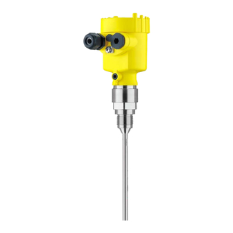
Tdr sensor for continuous level and interface measurement of liquids
Hide thumbs
Also See for VEGAFLEX 81:
- Operating instructions manual (100 pages) ,
- Quick setup manual (24 pages) ,
- Mounting instructions (20 pages)

Related Manuals for Vega VEGAFLEX 81


Summary of Contents for Vega VEGAFLEX 81
- Page 1 Operating Instructions TDR sensor for continuous level and interface measurement of liquids VEGAFLEX 81 Profibus PA Rod and cable probe Document ID: 44217...
-
Page 2: Table Of Contents
Parameter adjustment with PACTware ................52 Set up with the quick setup ..................... 53 Saving the parameterisation data ................... 55 Set up with other systems ....................56 DD adjustment programs ....................56 Diagnostics and servicing ....................57 Maintenance ........................57 VEGAFLEX 81 • Profibus PA... - Page 3 Safety instructions for Ex areas Take note of the Ex specific safety instructions for Ex applications. These instructions are attached as documents to each instrument with Ex approval and are part of the operating instructions. Editing status: 2021-08-19 VEGAFLEX 81 • Profibus PA...
-
Page 4: About This Document
Symbols used Document ID This symbol on the front page of this instruction refers to the Docu- ment ID. By entering the Document ID on www.vega.com you will reach the document download. Information, note, tip: This symbol indicates helpful additional infor- mation and tips for successful work. -
Page 5: For Your Safety
During work on and with the device, the required personal protective equipment must always be worn. Appropriate use VEGAFLEX 81 is a sensor for continuous level measurement. You can find detailed information about the area of application in chapter "Product description". -
Page 6: Namur Recommendations
The environment management system is certified according to DIN EN ISO 14001. Please help us fulfil this obligation by observing the environmental instructions in this manual: • Chapter "Packaging, transport and storage" • Chapter "Disposal" VEGAFLEX 81 • Profibus PA... -
Page 7: Product Description
• Optionally integrated Bluetooth module The further scope of delivery encompasses: • Documentation – Quick setup guide VEGAFLEX 81 – Instructions for optional instrument features – Ex-specific "Safety instructions" (with Ex versions) – If necessary, further certificates Information: Optional instrument features are also described in this operating instructions manual. - Page 8 Alternatively, you can access the data via your smartphone: • Download the VEGA Tools app from the "Apple App Store" or the "Google Play Store" • Scan the QR-code on the type label of the device or •...
-
Page 9: Principle Of Operation
3 Product description Principle of operation Application area The VEGAFLEX 81 is a level sensor with cable or rod probe for continuous level or interface measurement, suitable for applications in liquids. Functional principle - High frequency microwave pulses are guided along a steel cable or level measurement a rod. - Page 10 Example: upper medium dielectric constant 2, lower medium at least dielectric constant 12. Gas phase (L3) • Air or gas mixture • Gas phase - dependent on the application, gas phase does not always exist (d2 = 0) VEGAFLEX 81 • Profibus PA...
-
Page 11: Packaging, Transport And Storage
The integrated Bluetooth module (optional) enables wireless adjust- ment via standard adjustment devices. VEGACONNECT The interface adapter VEGACONNECT enables the connection of communication-capable instruments to the USB interface of a PC. VEGAFLEX 81 • Profibus PA... - Page 12 You can find further information in the operating instructions manual "Bypass tube VEGAPASS 81". Centering If you mount the VEGAFLEX 81 in a bypass tube or standpipe, you have to avoid contact to the bypass tube by using a spacer at the probe end.
- Page 13 Cables with a diameter up to 8 mm (0.315 in) can thus be strained. For this purpose there is an internal thread (M12 or M8) in the gravity weight. VEGAFLEX 81 • Profibus PA...
-
Page 14: Mounting
For safety reasons, the instrument must only be operated within the permissible process conditions. You can find detailed information on the process conditions in chapter "Technical data" of the operating instructions or on the type label. VEGAFLEX 81 • Profibus PA... -
Page 15: Mounting Instructions
When mounting rod or cable probes in vessels without metal walls, e.g. in plastic vessels, the measured value can be influenced by strong electromagnetic fields (emitted interference according to EN 61326: class A). In this case, use a probe with coaxial version. VEGAFLEX 81 • Profibus PA... - Page 16 You can find further information under "Setup procedure". DN25 ... DN150 ≤ 150 mm (5.91") > DN150 ... DN200 ≤ 100 mm (3.94") Fig. 6: Mounting socket When welding the nozzle, make sure that the nozzle is flush with the vessel top. VEGAFLEX 81 • Profibus PA...
- Page 17 These blocking distances for different mediums are listed in chapter "Technical data". Keep in mind for the adjustment that the default setting for the measuring range refers to water. VEGAFLEX 81 • Profibus PA...
- Page 18 If durability is no problem, we recommend the use of uncoated metal standpipes. When the VEGAFLEX 81 is used in bypass tubes, contact with the tube wall must be avoided. We recommend for this purpose a cable probe with centering weight.
- Page 19 It does not matter if the standpipe is perforated or slotted for better mixing. Measuring probes can be mounted in standpipes up to DN 200. VEGAFLEX 81 • Profibus PA...
- Page 20 If durability is no problem, we recommend the use of uncoated metal standpipes. When the VEGAFLEX 81 is used in standpipes, contact with the tube wall must be avoided. We recommend for this purpose a cable probe with centering weight.
- Page 21 If there is a risk of the cable probe touching the vessel wall during operation due to product movements or agitators, etc., the measuring probe can be strained. For this purpose there is an internal thread (M12 or M8) in the gravity weight. VEGAFLEX 81 • Profibus PA...
- Page 22 To compensate for the resulting changes in signal runtime, let the instrument determine the probe length automatically. You can find further information in the supplementary instructions of the rod and cable components. VEGAFLEX 81 • Profibus PA...
-
Page 23: Connecting To Power Supply
Note: Prior to setup you have to replace these protective caps with ap- proved cable glands or close the openings with suitable blind plugs. VEGAFLEX 81 • Profibus PA... -
Page 24: Connecting
1 cm (0.4 in) of insulation from the ends of the individual wires 5. Insert the cable into the sensor through the cable entry Fig. 13: Connection steps 5 and 6 Single chamber housing Double chamber housing 6. Insert the wire ends into the terminals according to the wiring plan VEGAFLEX 81 • Profibus PA... -
Page 25: Wiring Plan, Single Chamber Housing
Selection switch for instrument address For external display and adjustment unit Ground terminal for connection of the cable screening Wiring plan, double chamber housing The following illustration applies to the non-Ex, Ex-ia and Ex-d ver- sion. VEGAFLEX 81 • Profibus PA... - Page 26 Selection switch for bus address Connection compartment 6 7 8 Fig. 16: Connection compartment - double chamber housing Voltage supply, signal output For display and adjustment module or interface adapter For external display and adjustment unit Ground terminal for connection of the cable screening VEGAFLEX 81 • Profibus PA...
-
Page 27: Double Chamber Housing With Vegadis-Adapter
Fig. 18: Top view of the M12 x 1 plug connector Pin 1 Pin 2 Pin 3 Pin 4 Contact pin Colour, connection ca- Terminal, electronics ble in the sensor module Pin 1 Brown Pin 2 White Pin 3 Blue Pin 4 Black VEGAFLEX 81 • Profibus PA... -
Page 28: Wiring Plan - Version Ip66/Ip68, 1 Bar
6 7 8 Fig. 20: Address selection switch Addresses <100 (selection 0), addresses >100 (selection 1) Decade of the address (selection 0 to 9) Unit position of the address (selection 0 to 9) VEGAFLEX 81 • Profibus PA... -
Page 29: Switch-On Phase
The addressing procedure is described in the operating instructions manual "Display and adjustment module. Switch-on phase After connecting VEGAFLEX 81 to the bus system, the device first performs a self-test: • Internal check of the electronics •... -
Page 30: Set Up With The Display And Adjustment Module
The display and adjustment module is powered by the sensor, an ad- ditional connection is not necessary. Fig. 21: Installing the display and adjustment module in the electronics compart- ment of the single chamber housing VEGAFLEX 81 • Profibus PA... -
Page 31: Adjustment System
– Confirm selected menu – Edit parameter – Save value • [->] key: – Change measured value presentation – Select list entry – Select editing position • [+] key: – Change value of the parameter VEGAFLEX 81 • Profibus PA... -
Page 32: Parameter Adjustment - Quick Setup
Any values not confirmed with [OK] will not be saved. Switch-on phase After switching on, the VEGAFLEX 81 carries out a short self-test where the device software is checked. The output signal transmits a fault signal during the switch-on phase. -
Page 33: Parameter Adjustment - Extended Adjustment
"Setup" should be selected one after the other and provided with the correct parameters. If possible, go through the items in the given sequence. The procedure is described below. The following submenu points are available: VEGAFLEX 81 • Profibus PA... - Page 34 Hardware addressing is effective if an address less than 126 is set with the address selection switches on the electronics module of VEGAFLEX 81. In such case, software addressing has no effect - only the set hardware address applies. Software addressing Software addressing is only effective if address 126 or higher is set on the instrument with the address selection switches.
- Page 35 You have the option of choosing the demonstration mode. This mode is only suitable for test and demonstration purposes. In this mode, the sensor ignores the parameters of the application and reacts immedi- ately to any change. VEGAFLEX 81 • Profibus PA...
- Page 36 If you want the dielectric constant to be determined by the instrument, you have to enter the measured or known distance to the interface. Note: The dielectric constant can only be reliably determined if two different media and a sufficiently large interface are present. VEGAFLEX 81 • Profibus PA...
- Page 37 The distance refers tot he sensor reference plane (seal surface of the process fitting). Max. adjustment interface This menu item is only available if you have selected interface meas- urement under the menu item "Application". VEGAFLEX 81 • Profibus PA...
- Page 38 This should be done with the lowest possible level so that all potential interfering reflections can be detected. Proceed as follows: Select first if the probe is covered or uncovered. VEGAFLEX 81 • Profibus PA...
- Page 39 "Display". Warning: If a linearisation curve is selected, the measuring signal is no longer necessarily linear to the filling height. This must be considered by the VEGAFLEX 81 • Profibus PA...
- Page 40 Since the adjustment is very comprehensive, the menu points of Function Blocks 1 (FB1) were put together in a submenu. AI FB1 - Channel In menu item"Channel" you determine which measured value the output refers to. VEGAFLEX 81 • Profibus PA...
- Page 41 Select menu items and show data • Read data from the sensor into the display and adjustment module Caution: When the PIN is active, adjustment via PACTware/DTM as well as other systems is also blocked. VEGAFLEX 81 • Profibus PA...
- Page 42 In this menu item, you define the display format of the measured value on the display. You can define different display formats for the two measured values. You can thus define the number of decimal positions the measured value is displayed with. VEGAFLEX 81 • Profibus PA...
- Page 43 The two values are displayed in the menu item "Peak values, measurement reliability". The measurement can be influenced by the process conditions. In this menu item, the measurement reliability of the level measure- VEGAFLEX 81 • Profibus PA...
- Page 44 With the following functions you can zoom part sections of the echo curve. • "X-Zoom": Zoom function for the meas. distance • "Y-Zoom": 1, 2, 5 and 10x signal magnification in "V" • "Unzoom": Reset the presentation to the nominal measuring range without magnification VEGAFLEX 81 • Profibus PA...
- Page 45 PACTware. With the adjustment software PACTware and the PC the high-reso- lution echo curve can be displayed and used later on to assess the quality of the measurement. VEGAFLEX 81 • Profibus PA...
- Page 46 Measurement loop name Sensor Units Distance unit: order-specific Temperature unit: order-specific Probe length Länge der Messsonde factory setting Type of medium Liquid Application Level in the vessel Medium, dielectric constant Water-based, > 10 Superimposed gas phase VEGAFLEX 81 • Profibus PA...
- Page 47 AI FB1 Hysteresis 0.50 % AI FB1 Fail Safe Mode (behaviour in case of malfunction) Last Valid Out Value (last valid measured value) AI FB1 Fail Safe Value 0.00 % AI FB1 Target Mode Auto VEGAFLEX 81 • Profibus PA...
- Page 48 Primary Value (lin. percent level) AI FB2 scaling PV Scale (min.) AI FB2 scaling PV Scale (max.) 100 % AI FB2 Lin. Type Linear AI FB2 Out Scale Unit AI FB2 Out Scale Decimal Point #.## VEGAFLEX 81 • Profibus PA...
- Page 49 Write into sensor: Store data from the display and adjustment module back into the sensor The following data or settings for adjustment of the display and ad- justment module are saved: • All data of the menu "Setup" and "Display" VEGAFLEX 81 • Profibus PA...
- Page 50 In exceptional cases, individual parameters can be modified in order to adapt the sensor to special requirements. Change the settings of the special parameters only after having con- tacted our service staff. VEGAFLEX 81 • Profibus PA...
-
Page 51: Saving The Parameterisation Data
In the display and adjust- If the instrument is equipped with a display and adjustment module, ment module the parameter adjustment data can be saved therein. The procedure is described in menu item "Copy device settings". VEGAFLEX 81 • Profibus PA... -
Page 52: Setup With Pactware
Further setup steps are described in the operating instructions manu- al "DTM Collection/PACTware" attached to each DTM Collection and which can also be downloaded from the Internet. Detailed descrip- tions are available in the online help of PACTware and the DTMs. VEGAFLEX 81 • Profibus PA... -
Page 53: Set Up With The Quick Setup
The standard version is available as a download under www.vega.com/downloads and "Software". The full version is avail- able on CD from the agency serving you. Set up with the quick setup... - Page 54 2 Extended adjustment Maintenance Quick setup With quick setup you can carry out the parameter adjustment of VEGAFLEX 81 for your application in just a few simple steps. The assistant-driven adjustment includes the basic settings for simple, reliable setup and commissioning. Information: If the function is inactive, then possibly no instrument is connected.
-
Page 55: Saving The Parameterisation Data
7 Setup with PACTware Saving the parameterisation data We recommend documenting or saving the parameterisation data via PACTware. That way the data are available for multiple use or service purposes. VEGAFLEX 81 • Profibus PA... -
Page 56: Set Up With Other Systems
Set up with other systems DD adjustment programs Device descriptions as Enhanced Device Description (EDD) are available for DD adjustment programs such as, for example, AMS™ and PDM. The files can be downloaded at www.vega.com/downloads under "Software". VEGAFLEX 81 • Profibus PA... -
Page 57: Diagnostics And Servicing
• Switch-on and switch-off times • Status messages (according to NE 107) • Error messages (according to NE 107) The data are read out via a PC with PACTware/DTM or the control system with EDD. VEGAFLEX 81 • Profibus PA... -
Page 58: Status Messages
This status message is always active. It cannot be deactivated by the user. Function check: The instrument is being worked on, the measured value is temporarily invalid (for example during simulation). This status message is inactive by default. VEGAFLEX 81 • Profibus PA... - Page 59 Disconnect operating voltage briefly munication Communication Send instrument for repair error F125 Temperature of the electronics in the Check ambient temperature Bit 7 non-specified range Impermissible Insulate electronics electronics tem- Use instrument with higher temper- perature ature range VEGAFLEX 81 • Profibus PA...
- Page 60 S601 Level echo in the close range not Reduce level Bit 24 available Overfilling 100 % adjustment: Increase value Check mounting socket Remove possible interfering signals in the close range Use coaxial probe VEGAFLEX 81 • Profibus PA...
-
Page 61: Rectify Faults
The operator of the system is responsible for taking suitable meas- tion occurs ures to rectify faults. Fault rectification The first measures are: • Evaluation of fault messages • Checking the output signal • Treatment of measurement errors VEGAFLEX 81 • Profibus PA... - Page 62 Amplitude or position of a false signal Determine the reason for the changed has changed (e.g. buildup); false signal false signals, carry out false signal sup- time suppression no longer matches pression, e.g. with buildup VEGAFLEX 81 • Profibus PA...
- Page 63 Measured value remains re- Stored false signals in this position are Delete false signal suppression producible in one position larger than the level echo Carry out a new false signal suppression during emptying time VEGAFLEX 81 • Profibus PA...
- Page 64 Amplitude or position of a false signal has Determine the reason for the changed false changed (e.g. condensation, buildup); false signals, carry out false signal suppression, signal suppression no longer matches ac- e.g. with condensation time tual conditions VEGAFLEX 81 • Profibus PA...
- Page 65 100 % dur- range by editing ing emptying With bulk solids use radar sensor with purg- ing air connection or flexible antenna cover time VEGAFLEX 81 • Profibus PA...
-
Page 66: Exchanging The Electronics Module
24 hour service hotline Should these measures not be successful, please call in urgent cases the VEGA service hotline under the phone no. +49 1805 858550. The hotline is also available outside normal working hours, seven days a week around the clock. -
Page 67: Exchanging The Cable/Rod
(see "Setup procedure, Carry- ing out min. adjustment - Carrying out max. adjustment"). The rod or cable of the probe can be shortened individually. Shorten cable/rod 1. Mark the requested length with mounted measuring rod. 2. Cable: Loosen the pins on the gravity weight (hexagon 3) VEGAFLEX 81 • Profibus PA... -
Page 68: Software Update
Current instrument software as file You can find the current instrument software as well as detailed information on the procedure in the download area of our homepage: www.vega.com. You can find information about the installation in the download file. VEGAFLEX 81 • Profibus PA... -
Page 69: How To Proceed If A Repair Is Necessary
Attach the completed form and, if need be, also a safety data sheet outside on the packaging • Ask the agency serving you to get the address for the return ship- ment. You can find the agency on our homepage. VEGAFLEX 81 • Profibus PA... -
Page 70: Dismount
Pass the instrument directly on to a specialised recycling company and do not use the municipal collecting points. If you have no way to dispose of the old instrument properly, please contact us concerning return and disposal. VEGAFLEX 81 • Profibus PA... -
Page 71: Supplement
Ʋ Cable gland PA, stainless steel, brass Not suitable for hot steam applications >150 °C (>302 °F). In this case, use a device with a ceramic-graphite seal. Aluminium, stainless steel precision casting and Ex d housing VEGAFLEX 81 • Profibus PA... - Page 72 Ʋ Rod: ø 12 mm (0.472 in) up to 6 m (19.69 ft) Ʋ Trimming accuracy - Rod ±(1 mm + 0.05 % of the rod length) Ʋ Cable: ø 2 mm (0.079 in) up to 75 m (246.1 ft) VEGAFLEX 81 • Profibus PA...
- Page 73 Number of FBs with AI (function blocks with analogue input) Default values Ʋ 1. FB Primary Value (filling height linearized in %) Ʋ 2. FB Secondary Value 1 (filling height in %) Ʋ 3. FB Secondary Value 2 (distance value) VEGAFLEX 81 • Profibus PA...
- Page 74 Ʋ Medium Water/Oil (dielectric constant ~2.0) Ʋ Mounting Probe end does not touch the vessel bottom Sensor parameter adjustment No gating out of false signals carried out With interface measurement = 2.0. VEGAFLEX 81 • Profibus PA...
- Page 75 Depending on the mounting conditions, deviations can occur which can be rectified by adapting the adjustment or changing the measured value offset in the DTM service mode. The blocking distances can be optimized via a false signal suppression. VEGAFLEX 81 • Profibus PA...
- Page 76 -2 mm (-0.079 ") -10 mm (-0.591 ") 0,15 m 0,3 m 0,07 m (5.906 (11.811 " ") (2.756 ") 0,05 m (1.97 ") Fig. 34: Deviation VEGAFLEX 81 in rod version in oil Blocking distance (no measurement possible in this area) Probe length VEGAFLEX 81 • Profibus PA...
- Page 77 0,08 m (3.15 ") Fig. 36: Deviation VEGAFLEX 81 in cable version (ø 2 mm/0.079 in), in medium oil Blocking distance (no measurement possible in this area) When using a centering weight, it is only possible to measure up to the upper edge of the cerntering weight. Probe length VEGAFLEX 81 • Profibus PA...
- Page 78 2 mm (0.079 ") -2 mm (-0.079 ") -15 mm (-0.591 ") 0,1 m 0,2 m 0,07 m (3.937 (7.874 " " (2.756 ") Fig. 38: Deviation VEGAFLEX 81 in cable version (ø 4 mm/0.157 in, PFA-coated) in water Blocking distance (no measurement possible in this area) Probe length VEGAFLEX 81 • Profibus PA...
- Page 79 200 °C (392 °F) -0.02 % 0.05 % 0.37 % 400 °C (752 °F) -0.02 % 0.03 % 0.25 % Steam (saturated 100 °C (212 °F) 0.26 % steam) 150 °C (302 °F) 0.17 % 2.1 % VEGAFLEX 81 • Profibus PA...
- Page 80 Time span after a sudden measuring distance change by max. 0.5 m in liquid applications, max 2 m with bulk solids applications, until the output signal has taken for the first time 90 % of the final value (IEC 61298-2). VEGAFLEX 81 • Profibus PA...
- Page 81 -40°C / -40°F Fig. 41: Ambient temperature - process temperature, version with temperature adapter Ambient temperature Process temperature (depending on the seal material) Aluminium housing Plastic housing Stainless steel housing, precision casting Stainless steel housing, electropolished VEGAFLEX 81 • Profibus PA...
- Page 82 Ʋ Max. length 180 m (590.6 ft) Ʋ Min. bending radius (at 25 °C/77 °F) 25 mm (0.984 in) Ʋ Diameter approx. 8 mm (0.315 in) Ʋ Colour - Non-Ex version Black Ʋ Colour - Ex-version Blue VEGAFLEX 81 • Profibus PA...
- Page 83 IP66/IP68 (0.2 bar) Type 6P IP66/IP68 (1 bar) Double chamber IP66/IP68 (0.2 bar) Type 6P IP66/IP68 (1 bar) Stainless steel (electro-pol- Single chamber IP66/IP68 (0.2 bar) Type 6P ished) Galvanic separation between electronics and metal housing parts VEGAFLEX 81 • Profibus PA...
-
Page 84: Device Communication Profibus Pa
Instrument ID GSD file name VEGA Instrument class in VEGA Profile-specific profile 3.02 VEGAFLEX 80 se- 0xBF5 0x9702 VE010BF5.GSD PA139702.GSD ries Cyclical data traffic The Primary class 1 (e.g. PLC) cyclically reads out measured values from the sensor during opera- VEGAFLEX 81 • Profibus PA... - Page 85 The below block diagram below shows which data can be accessed by the PLC. Fig. 42: VEGAFLEX 81: Block diagram with AI FB 1 … AI FB 3 OUT values TB Transducer Block FB 1 … FB 3 Function Block Module of the PA sensors For the cyclic data traffic, VEGAFLEX 81 provides the following modules: • AI FB1 (OUT) – Out value of the AI FB1 after scaling • AI FB2 (OUT) –...
- Page 86 Fig. 44: Data format of the measured value Coding of the status byte associated with the PA output value You can find further information for the coding of the status byte in the Device Description 3.02 on VEGAFLEX 81 • Profibus PA...
-
Page 87: Dimensions
- low limited 0 x 8e good (non-cascade) - ac- Hi-Hi-Alarm tive critical alarm - high limited 11.3 Dimensions The following dimensional drawings represent only an extract of all possible versions. Detailed VEGAFLEX 81 • Profibus PA... - Page 88 11 Supplement dimensional drawings can be downloaded at www.vega.com/downloads under "Drawings". Plastic housing ~ 69 mm ~ 84 mm (2.72") (3.31") ø 79 mm ø 79 mm (3.11") (3.11") M16x1,5 M20x1,5/ ½ NPT M20x1,5/ ½ NPT Fig. 45: Housing versions in protection IP66/IP67 (with integrated display and adjustment module the housing is 9 mm/0.35 in higher)
- Page 89 Fig. 48: Housing versions with protection rating IP66/IP68 (0.2 bar), (with integrated display and adjustment mod- ule the housing is 9 mm/0.35 in higher) Stainless steel single chamber (electropolished) Stainless steel single chamber (precision casting) Stainless steel double chamber housing (precision casting) VEGAFLEX 81 • Profibus PA...
- Page 90 Fig. 49: Housing version with protection rating IP66/IP68 (1 bar), (with integrated display and adjustment module the housing is 9 mm/0.35 in higher) Stainless steel single chamber (electropolished) Stainless steel single chamber (precision casting) Stainless steel double chamber housing (precision casting) VEGAFLEX 81 • Profibus PA...
- Page 91 11 Supplement VEGAFLEX 81, cable version with gravity weight SW 36 (1.42") (G¾, ¾ NPT) SW 41 (1.61") (G1, 1 NPT) SW 46 (1.81") (G1½, 1½ NPT) G¾, ¾ NPT, G1, 1 NPT, G1½, 1½ NPT ø 4 mm ø 4 mm (0.16")
- Page 92 11 Supplement VEGAFLEX 81, cable version with centering weight SW 36 (1.42") (G¾, ¾ NPT) SW 41 (1.61") (G1, 1 NPT) SW 46 (1.81") (G1½, 1½ NPT) G¾, ¾ NPT, G1, 1 NPT, G1½, 1½ NPT ø 4 mm ø 4 mm (0.16")
- Page 93 G1½, 1½ NPT G1½, 1½ NPT ø 8 mm ø 12 mm (0.47") (0.32") Fig. 52: VEGAFLEX 81, threaded version Sensor length, see chapter "Technical data" Rod version ø 8 mm (0.315 in) Rod version ø 12 mm (0.472 in) VEGAFLEX 81 • Profibus PA...
-
Page 94: Industrial Property Rights
Les lignes de produits VEGA sont globalement protégées par des droits de propriété intellec- tuelle. Pour plus d'informations, on pourra se référer au site www.vega.com. VEGA lineas de productos están protegidas por los derechos en el campo de la propiedad indus- trial. Para mayor información revise la pagina web www.vega.com. - Page 95 Repair 69 – Rectification 61 Replacement parts Fault rectification 61 – Bypass 12 Functional principle 9 – Display and adjustment module with heating 12 – Fixing facility 13 Gas phase 36 – Rod components 12 VEGAFLEX 81 • Profibus PA...
- Page 96 Scaling unit 41 Sensor characteristics 51 Service hotline 66 Simulation 45 Software addressing 29, 34 Special parameters 50 Status bytes PA output value 86 Telegram configuration 86 Type label 7 Type of medium 35 Units 35 VEGAFLEX 81 • Profibus PA...
- Page 97 Notes VEGAFLEX 81 • Profibus PA...
- Page 98 Notes VEGAFLEX 81 • Profibus PA...
- Page 99 Notes VEGAFLEX 81 • Profibus PA...
- Page 100 Subject to change without prior notice © VEGA Grieshaber KG, Schiltach/Germany 2021 VEGA Grieshaber KG Am Hohenstein 113 Phone +49 7836 50-0 77761 Schiltach E-mail: info.de@vega.com...
Need help?
Do you have a question about the VEGAFLEX 81 and is the answer not in the manual?
Questions and answers