Advertisement
Quick Links
Advertisement

Related Manuals for Ofs Porter


Summary of Contents for Ofs Porter
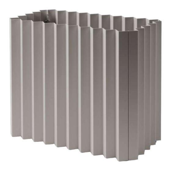
- Page 1 Porter assembly instructions...
- Page 2 Porter assembly instructions Table of contents Components Planter assembly Configuration notes Adjusting planter connections 9-10 ofs.com imagine a place® 800.521.5381 Assembly instructions...
- Page 3 Porter assembly instructions Components 4x panels 8x top/shelf 4x leveler cam locks cam locks Tray support Tray liner ofs.com imagine a place® 800.521.5381 Assembly instructions...
- Page 4 Porter assembly instructions Planter assembly Set two panels next to each other as shown. Each flange is labeled, so ensure that you match them accordingly (A to A, B to B, etc.). (Figure A) Begin assembly with the leveler cam locks first. Insert a leveler cam lock into the bottom hole from left to right.
- Page 5 Porter assembly instructions Planter assembly continued Engage cam by pivoting it upward until it stops. Assemble all four panels in this manner. (Figure C) Decide which height you want your tray at. If you want your tray in the bottom position, move to Step 5 now. If you want your tray at the middle height setting, skip to Step 5, then go to Step 6.
- Page 6 Porter assembly instructions Planter assembly continued For bottom tray position, Insert tray support from top. Then insert tray liner. The support and tray will rest on the leveler cam locks. (Figure E) Note: Tray limited to 100lbs If a middle shelf is desired, use an extra set of top /shelf cam locks in the center holes.
- Page 7 Porter assembly instructions Planter assembly continued Insert top cam through the holes at the top of every panel, joining two panels together. (Figure E) Engage cam by pivoting it downward until it clicks. (Figure F) Figure E Figure F ofs.com imagine a place®...
- Page 8 Porter assembly instructions Configuration notes Planters is intended to nest with other planters as shown here. (Figure A) In some configurations, your planter may end up being offset, as shown here. (Figure B) If you are unable to fix the problem by rotating a square planter, follow the Adjusting planter connections steps to rebuild ONLY the rectangular planters.
- Page 9 Porter assembly instructions Adjusting planter connections Remove top cams. (Figure A) Remove tray top and tray support from rectangular planters. (Figure B) Cam lock Figure A Tray liner Tray support Figure B ofs.com imagine a place® 800.521.5381 Assembly instructions...
- Page 10 Porter assembly instructions Adjusting planter connections continued Flip your planter upside down. (Figure C) Move leveler cam locks to the bottom holes. (Figure D) Figure C Move to bottom Figure D ofs.com imagine a place® 800.521.5381 Assembly instructions...
- Page 11 Porter assembly instructions Adjusting planter connections continued Insert tray support from top. Then insert tray liner. (Figure E) Re-install top cams. (Figure F) Tray liner Tray support Figure E Cam lock Figure F ofs.com imagine a place® 800.521.5381 Assembly instructions...
Need help?
Do you have a question about the Porter and is the answer not in the manual?
Questions and answers