Table of Contents
Advertisement
Quick Links
• TIP – You need solid opening and closing stops. The control board will search for these when
• TIP – You need to fit three small loops of wire to your safety inputs to make anything work. These
can be removed later if you install safety devices to these input terminals. But for now, take three
pieces of light gauge wire (speaker or telephone wire is good) about 50mm long and strip both ends
7mm and insert them as above from 7 to 8, 7 to 9 and 7 to 10.
• TIP – The STOP input will not seal unless you have the manual override handle closed.
• TIP – To program and to run all safety inputs need to be sealed. The LED lights 5,6,7 and 8 should all
• TIP – Start with dip switches 1 to 8 and 12 in the off position. You can adjust 9,10 and 11 to suit
• TIP – Do not install any accessories until after you have programmed the unit and have it operating
as you would like. You can then add each accessory one at a time.
• TIP – If using solar power refer to the manual for correct input power connection. When solar
powered the logic automatically enters power save mode and only LED 1&2 will work.
1. Ensure you have followed the instructions above and that you have the four green LED lights lit.
2. Carefully turn trimmer V-RAL anti clockwise until it comes to a stop. (Do nor force)
3. Release the gate and position it 500mm from the fully open stop.
4. Press the PROG button and hold until DL2 LED starts flashing orange. Release the button.
5. The gate should start to open slowly to find the open stop. If the gate closes instead remove power,
change the polarity of the motor by swapping terminals 23 and 24 and start again from point three.
6. When the opening stop is found the gate will close slowly searching for the closing stop.
7. When the closing stop is found the gate will run a full open and close before exiting programming.
8. If using remote controls press and release quickly CH1. Green LED2 should light to indicate ready.
9. In the next ten seconds press for one second and release one of the buttons on your remote
control. The green LED turns off and on again waiting for further remote controls.
10. When you have programmed all remote controls simply wait ten seconds until DL2 goes out.
12. You can now adjust and connect accessories one at a time and test each time.
Q u e s t i o n s – s e r v i c e @ a u t o m a t i c s o l u t i o n s . c o m . a u
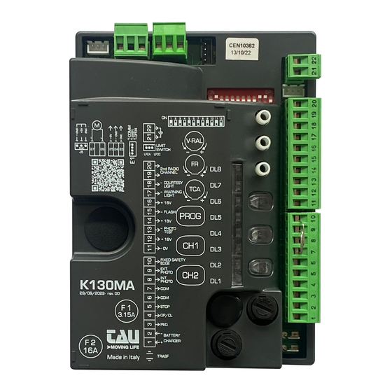
TAU 130MA
programming. Make sure they have no movement or flex.
be lit green. (Not so when solar powered)
your model of motor.
QUICKSTART
11. Test your install.
Page 1
Advertisement
Table of Contents

Subscribe to Our Youtube Channel
Related Manuals for tau K130MA


Summary of Contents for tau K130MA
- Page 1 TAU 130MA • TIP – You need solid opening and closing stops. The control board will search for these when programming. Make sure they have no movement or flex. • TIP – You need to fit three small loops of wire to your safety inputs to make anything work. These can be removed later if you install safety devices to these input terminals.
- Page 2 INSTALLATION GUIDE K130MA...
- Page 3 K130MA WIRING DIAGRAM Dip-switches 9 10 11 12 Trimmer: V-RAL 9 10 11 12 LFCA L V-RAL K130MA PROG LEDs: DL8 FIXED SAFETY EDGE EXT. PHOTO INT. PHOTO (SM) STOP OPEN/CLOSE PEDESTRIAN 3.15A ERRORS BATT TRAS...
-
Page 4: Power Supply
Aerial - Terminals 1 – 2: Careful NOT to invert polarity. - If Jumper J6 is plugged in, energy saving mode will be activated and, at the end of each manouvre, outputs 11-12, 12-13, 14-15, 16-17 and 16-18 will be switched off. Gate open Courtesy light Limit... - Page 5 CONNECTION OF BATTERY CHARGER + BATTERY (OPTIONAL) (FC) 9 10 11 12 LFCA LFCC V-RAL BATTERY CHARGER K130MA PROG ROSSO VERDE (SM) 3.15A BATTERY 12 V 7,2 Ah TRASF To ensure the gate operation during a power failure, the KB4 kit (battery charger + battery 12V 7.2Ah) can be used to connect to the control unit as shown in the diagram above.
-
Page 6: Solar Panel
CONNECTION OF SOLAR PANEL + ADJUSTMENT BOARD + BATTERY (OPTIONAL) SOLAR PANEL (FC) 9 10 11 12 LFCA LFCC V-RAL K130MA PROG (SM) ROSSO VERDE 3.15A BATTERY TRASF 12 V If you do not have the mains voltage to power the gate automation and you want to use renewable energy, you can connect a photovoltaic panel + adjustment board + 12V battery to the automation control unit as shown in the diagram above. -
Page 7: Installation
This product may only be installed and serviced by qualified personnel in compliance with current, laws, regulations and directives. When designing its products, TAU observes all applicable standards (please see the attached declaration of conformity) but it is of paramount importance that installers strictly observe the same standards when installing the system. -
Page 8: Technical Characteristics
STRIAN, etc.), in order to avoid gate malfunctions, it will be necessary to uncouple the various controls using RELAYS or using our 750T-RELE device. 2. INTRODUCTION The K130MA board has two working modes, selectable through the J6 jumper (see wiring diagram). J6 Not jumped: standard mode, i.e. the control unit is powered all the time;... - Page 9 STOP button N.C. input – Stops the automation in any position, temporarily pre- venting the automatic closure, if programmed. (5= STOP - 6= COM ) NOTE: A safety micro-switch is connected to the STOP push-button. In case 5 - 6 the STOP input remains open for more than 5 seconds, the operator will per- STOP form a cycle at a slow speed to reset the operating parameters to the values...
- Page 10 Motor supply output 18/24 V DC max. 200W. (26= POSITIVE - 27= NEGA- 26 - 27 MOTOR TIVE) Quick coupling for connection for limit switches. Notice: connect/disconnect the limit switches with the control unit OPTIONAL J2 (FC) LIMIT SWITCHES disconnected. It is advisable to wait 10 seconds before powering up the control unit again.
- Page 11 the automation ignores the closure command during opening and auto-close time NO REVERSE Off the automation responds as established by dip switch No. 2. On the pre-flashing function is enabled. PRE- FLASHING Off the pre-flashing function is disabled. On the “photocell test” function is enabled. FOTOTEST the “photocell test”...
- Page 12 IMPORTANT: Carry out the first stroke memorization with the RAL trimmer positioned fully turned counterclockwise (minimum deceleration speed). PROCEDURE WITHOUT LIMIT SWITCHES INSTALLED: 1. Start the procedure with the gate at approx. 0.5 m from the mechanical opening stop. If the automation closes instead of opening, stop the run of the gate (by cutting the photocells or closing the STOP contact), invert the polarity of the motor, take the gate at approx 0,5 m from the mechanical stop) and restart the procedure from the beginning.
-
Page 13: Obstacle Detection
Please remember that an obstacle during saving is interpreted as a mechanical limit stop (the system does not start any safety operation, it just stops the motor) 7. K130MA CHARACTERISTICS TIMER-OPERATED OPENING AND CLOSING CYCLES The opening/closing of the automation can be controlled by means of a timer that has a free N.O. - Page 14 obstacle for motor; 2 (red) flashes : Make sure there are no obstacles across the path of the gate and that it slides smoothly; With an active automatic closing feature, after the intervention meant to de- tect the obstacle, the automatic closing is deactivated. A command pulse is required to carry out the closing;...
- Page 15 DL3 - Red PEDESTRIAN button LED signal DL4 - Red OPEN/CLOSE button LED signal DL5 - Green STOP button LED signal DL6 - Green INTERNAL PHOTOCELLS LED signal DL7 - Green EXTERNAL PHOTOCELLS LED signal DL8 - Green SENSITIVE EDGE LED signal Multiple errors are signalled by a 2-second pause between signals.
-
Page 16: Memory Capacity
of CH1 (in this case the DL2 LED is yellow); 7_ to program transmitters into the third channel, repeat procedure from point 1 using CH1 and CH2 buttons at the same time (DL2 will turn on red); 8_ to exit the learning mode without memorising a code, press button CH1 or CH2 briefly. If the maximum number of radio controls is reached (30), the LED will begin to flash rapidly for about 3 seconds but without performing memorisation. - Page 17 Check that the new and old remote control use the same technology. 13. GUARANTEE: GENERAL CONDITIONS TAU guarantees this product for a period of 24 months from the date of purchase (as proved by the sales document, receipt or invoice).
- Page 18 Declares under its sole responsibility, that the product: Electronic control unit designed for automatic movement of: Sliding gates for use in a: Residential/Apartment building use complete with: Radioreceiver Model: K130MA Type: K130MA Serial number: see silver label Commercial name: Control panel for one 18V motor with encoder Has been produced for incorporation on an access point (sliding gate) of for assembly with other devices used to move such an access point, to constitute a machine in accordance with the Machinery Directive 2006/42/EC.
- Page 19 Via Enrico Fermi, 43 - 36066 Sandrigo (VI) - Italy Tel +39 0444 750190 - Fax +39 0444 750376 info@tauitalia.com - www.tauitalia.com Foglietto illustrativo CARTA - Raccolta differenziata. Segui le indicazioni del tuo comune. (N.B.: togliere i punti metallici) Instruction leaflet PAPER - Waste separation.
Need help?
Do you have a question about the K130MA and is the answer not in the manual?
Questions and answers