
Related Manuals for Posch SpaltFix S-360


Summary of Contents for Posch SpaltFix S-360
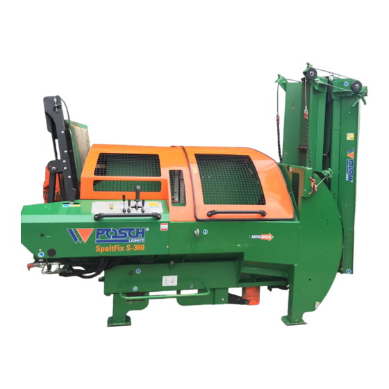
- Page 1 Operating Instructions SpaltFix S-360 D1010473 - V001 *D1010473-V001* English Copyright by Posch Gesellschaft m.b.H., Made in Austria...
- Page 2 Machine number:................Serial number:..................POSCH Austria: 8430 Leibnitz, Paul-Anton-Keller-Strasse 40, telephone: +43 (0) 3452/82954, fax: +43 (0) 3452/82954-53, e-mail: leibnitz@posch.com POSCH Germany: 84149 Velden/Vils, Preysingallee 19, telephone: +49 (0) 8742/2081, fax: +49 (0) 8742/2083, e-mail: velden@posch.com...
-
Page 3: Table Of Contents
Contents Contents Foreword Copyright notice Liability for defects Reservations Definitions Operating instructions Safety information Explanation of symbols General safety information Safety instructions for cut-splitters Safety instructions for conveyor belts Noise Remaining risks Proper use Incorrect use General Scope Description Major machine components Stickers and their meaning Set-up Folding down the feed... - Page 4 Contents Checks Protective guards Screw fittings Electrical equipment Hydraulic lines Saw blade V-belt tension Oil level Maintenance 10.1 Lubrication 10.2 Oil changing 10.3 Saw blade 10.4 Changing the V-belt 10.5 Splitting 10.6 Limit switch 10.7 Feed belt 10.8 Cleaning Special equipment 11.1 Conveyor belt 11.2...
-
Page 5: Foreword
Foreword Foreword Thank you for buying our product. This machine has been built in conformity with applicable European standards and regulations. These operating instructions explain how to operate the machine safely and efficiently and how to maintain it. Any person entrusted with the transport, installation, commissioning, operation or maintenance of the machine must have read and understood: ▪... -
Page 6: Operating Instructions
Foreword The operating personnel (operators) are those entrusted by the operator to operate the machine. Technical personnel Technical personnel are persons entrusted by the operator of the machine with special tasks such as installation, set-up, maintenance and troubleshooting. Electrician An electrician is a person who, by virtue of his specialist training, has knowledge of electrical systems, standards and regulations and is able to identify and prevent possible hazards. -
Page 7: Safety Information
Safety information Safety information Explanation of symbols The following symbols and instructions in this manual provide warnings about possible personal injury or property damage or give useful information about working with the machine. DANGER Warning about danger zones Instruction regarding safe working, where non-compliance entails the risk of serious or fatal injury. -
Page 8: General Safety Information
Never leave the machine running unattended. Switch off the machine's drive unit before carrying out any adjustments. Only use original - POSCH - spare parts. Do not modify or tamper with the machine. Work on electrical equipment must only be carried out by qualified electricians. -
Page 9: Safety Instructions For Cut-Splitters
Safety information Safety instructions for cut-splitters Prior to starting up the machine, the machine operator must agree the safety provisions with the operator for wood manipulation (crane, forklift, front-end loader, etc.) and must observe these safety provisions and the safety instructions from the wood manipulation operator. ▪... -
Page 10: Noise
It is up to the operating personnel to ensure that work is carried out safely. Proper use The SpaltFix S-360 is a cutting and splitting machine for logs with a diameter of 7 - 35 cm. Using pre-split firewood can lead to a lower level of firewood quality and decreased performance of the machine. -
Page 11: General
Cross conveyors are available in lengths of 2.2 / 3.2 and 4.2 m - with 2 to 4 chain strands Description The SpaltFix S-360 machine is a firewood processing machine which is used to cut and then split firewood. The log is cut in a horizontal position and is held in place with the claw while being cut. -
Page 12: Major Machine Components
General A choice of options is available for discharging the split logs, e.g. via a conveyor belt. The cutting and splitting tool is hydraulically driven. The machine is driven by an electric motor or a pto. Major machine components Hold-down device Feed Splitter Operation - splitter... -
Page 13: Stickers And Their Meaning
General Stickers and their meaning Only operate with all guards and protective equipment in place Do not open or remove guards or protective equipment while the machine is in operation Caution, tool runs on Only carry out repair, set-up, maintenance and cleaning work when the drive is switched off and the tool is stationary. - Page 14 General Rotational direction of PTO Z2001220 Rotational direction of saw blade Z2001220 PTO speed Lifting point for forklift Z2001311 Oil level Z2001360 Maximum saw blade diameter max 900 mm min 890 mm 40 mm Z2001394 Lubrication point Z2050400 Stickers on controls Stop Feed (forwards) Feed (backwards)
- Page 15 General Stickers on belt conveyor Danger zone Z2001162 Maximum angle (on conveyor belt) Z2001206 Lubrication point Z2050400 Stickers on longitudinal conveyor Danger zone Z2001162 Caution, moving tools Lubrication point Z2050400 Stickers on the cross-conveyor Danger zone Z2001162 Maximum weight load max.
-
Page 16: Set-Up
Set-up Set-up Ensure the machine is stable before starting it. Set up the machine on a level, firm and clear work surface. The machine must be placed directly on the ground. Do not place wooden boards, flat pieces of metal etc. underneath it. The machine must not be set up under an overhead electrical power line. -
Page 17: Start-Up
Start-up Start-up Before starting to operate the machine, please check that the protective and safety systems are working and also the hydraulic hoses and oil level. Before each start-up, the condition of the electrical cables must be checked. Check that the saw blade is firmly seated before each use. If a fault occurs during operation, the machine must be shut down immediately and secured so it cannot be switched on accidentally or started-up by unauthorised persons. -
Page 18: Driven By Tractor Via Cardan Shaft (Type Z)
Start-up A tight plug connection can rip the CEE plug out of the switch housing. ▪ This can be remedied using standard plugs and a silicone spray. Any such damage to the switch is not covered by the guarantee. 5.1.2 Control box 5.1.2.1 Functions on the control box... - Page 19 Start-up ▪ Slowly engage the tractor PTO shaft and allow the machine to start moving. ▪ Set the required PTO shaft speed using the manual throttle. Maximum PTO shaft speed: ▪ 480 rpm The maximum PTO shaft speed must on no account be exceeded, otherwise the oil will become too hot.
-
Page 20: Operation
Operation Operation At outdoor temperatures below 0°C, let the machine idle for approximately five minutes to allow the hydraulic system to reach the correct operating temperature (the hydraulic pipes will then be warm to the touch). Work operation Only one person may operate the machine at a time. Ensure that no other people are in the vicinity of the machine. - Page 21 Operation 6.1.1.1 Notes on sawing The drive must always be switched off before clearing a blockage. 6.1.1.2 Notes on splitting Only use logs up to a diameter of 7 - 35 cm. Logs must be pushed longitudinally towards the splitting blade. ▪...
-
Page 22: Feed
Operation Feed Snap-in lock Cotter pin Stabiliser foot Feed Support holder Working position: ▪ Open the snap-in lock by turning it. ▪ Unlock and remove the connecting pin. ▪ Fold down the feed. – Make sure the support foot fits in the support foot holder. –... -
Page 23: Splitting Knife
Operation Splitting knife 6.3.1 Changing the splitting knife Clip pin Splitting knife Splitting knife pin Removing: ▪ Remove the clip pin. ▪ Support the splitting knife to prevent it from falling down. ▪ Pull out the splitting knife pin. ▪ Lift the splitting knife clear. Installing: ▪... - Page 24 Operation 6.3.2 Splitting knife support Hexagon bolt Splitting knife support Removing: ▪ Undo the four hexagon bolts. ▪ Tilt the splitting knife support forwards and pull it out upwards. Installing: ▪ Proceed as above but in the reverse order.
-
Page 25: Put Out Of Operation
Put out of operation Put out of operation Before switching off the machine, depressurise all hydraulic functions by placing all control levers in the neutral position. Switching off the machine Driven by electric motor (Type E) Type E22 ▪ Move the switch to the 0 position. Driven by tractor via universal joint shaft (type PZG) ▪... -
Page 26: Transport
Transport Transport Before transport, it is vital to switch off the drive and secure it so it cannot be switched on accidentally or started-up by unauthorised persons. Disconnect the machine from the mains. ▪ In addition, pull out the plug of the device. ▪... -
Page 27: Lifting With A Crane
Transport Observe the road traffic regulations when driving on public highways. Maximum transport speed: 25 km/h When the machine is uncoupled from the tractor, it must be placed on a firm, level surface. Lifting with a crane Lifting gear Lifting eye When using a crane, only lift the machine by the lifting eyes. -
Page 28: Checks
Checks Checks Before control work on the machine, it is vital to switch off the drive and secure it so it cannot be switched on accidentally or started-up by unauthorised persons. Disconnect the machine from the mains. ▪ In addition, pull out the plug of the device. ▪... -
Page 29: Hydraulic Lines
Checks Hydraulic lines After the first hour of operation, check that all hydraulic connections are secure and are not leaking. Check that all hydraulic connections are secure and are not leaking after every further 100 hours of operation. ▪ Damaged hydraulic lines must be replaced immediately. Saw blade Check that the saw blade is firmly seated before each use. - Page 30 Checks 9.7.2 Transmission oil level Oil inlet screw Oil drain screw Oil level screw If the oil seeps out of the hole of the oil level screw when the machine is on level ground, the maximum oil level has been reached. If the oil level is below the hole, this is the minimum oil level.
-
Page 31: Maintenance
▪ Remove the universal joint shaft from the tractor. Work on electrical equipment must only be carried out by qualified electricians. Never work without the protective guards in place. Only use original - POSCH - spare parts. 10.1 Lubrication Dispose of oily and greasy parts and oil residues in accordance with legal regulations. - Page 32 Maintenance 10.2.1 Changing the hydraulic oil The first oil change should be carried out after 500 operating hours, all further oil changes should then be carried out after every 1000 operating hours or annually. Oil inlet screw Oil sight glass Oil drain screw ▪...
- Page 33 Maintenance Recommended hydraulic oils Manufacturer Oil specification ATF II SHELL Donax TA Hydrelf DS 46 ESSO Univis N46 CASTROL Hyspin AWH-M 46 ARAL Vitam VF46 GENOL Hydraulic oil 520 FUCHS Plantohyd 32S * / Renolin B46 HVI *..biological hydraulic oils 10.2.2 Oil filter Filter cover...
-
Page 34: Saw Blade
10.3 Saw blade Always wear protective gloves when handling saw blades. Only strengthened POSCH saw blades may be used. Standard saw blades are too weak and pose a safety risk. Observe the maximum saw blade speed specified by the manufacturer. - Page 35 Maintenance ▪ Hold the circular saw shaft with the spring flange wrench and undo the clamping nut with the circular saw wrench. ▪ Remove the spring flange and the saw blade. ▪ Put the new blade in and secure it. The clamping nut must be screwed back on as it was before.
-
Page 36: Changing The V-Belt
Maintenance 10.4 Changing the V-belt 10.4.1 Tips on changing the V-belt If one V-belt is being changed, then all V-belts must be changed! The V-belts must be fitted loose. If they are "forced" onto the V-belt pulley, they may be damaged and quickly tear. - Page 37 Maintenance Cover - V-belt Adjustment plate PTO shaft cover Lock nut - tensioning screw Hexagon bolt - adjustment plate Tensioning screw ▪ Remove the cover for the V-belt and the PTO shaft cover. ▪ Undo the four hexagon bolts of the adjustment plate. ▪...
- Page 38 Maintenance 10.4.3 Changing the V-belts on PTO/electric drives Lock nut Tension spring Tensioning screw ▪ Loosen the lock nuts on both tensioning screws. ▪ Remove both tension springs from the saw feed completely. Cover - V-belt Adjustment plate PTO shaft cover Lock nut - tensioning screw Hexagon bolt - adjustment plate Tensioning screw...
- Page 39 Maintenance Guard plate Parallel key Allen screw Threaded pin Coupling part – electric motor Hexagon nut Coupling hub Bearing flange Coupling part - transmission ▪ Undo the hexagon bolts of the guard plate and remove the plate. ▪ Loosen the Allen screws from the coupling parts. ▪...
-
Page 40: Splitting
Maintenance 10.5 Splitting Lock nut Valve shut-off rod Shut-off rod If the splitter pusher does not automatically retract, proceed as follows: ▪ Remove the front control panel and guard plate. ▪ Undo the lock nuts and turn inwards slightly - the shut-off rod will be shortened slightly. ▪... -
Page 41: Cleaning
Maintenance 10.7.2 Conveyor belt - ensuring the machine is running centrally Conveyor belt Tensioning screw Return drum Lock nut If the conveyor belt is not running centrally on the drive and/or return drum, it is possible to adjust the direction of travel. ▪... -
Page 42: Special Equipment
Special equipment Special equipment 11.1 Conveyor belt 11.1.1 Conveyor belt types Conveyor belt type Conveyor belt length Conveyor height Belt width 150 cm 100 cm 30 cm 400 cm 250 cm 30 cm 500 cm 300 cm 30 cm 11.1.2 Set up conveyor belt Spring cotter Rope winch... - Page 43 Special equipment Setting the conveyor belt angle: ▪ Crank the conveyor belt to the desired height using the rope winch. ▪ Mount the chain on both sides in this position. – The smallest angle is achieved with the whole chain length. –...
-
Page 44: Volumecontrol
Special equipment 11.1.5 Maintenance - conveyor belt 11.1.5.1 Notes regarding the conveyor belt Check that the belt is running centrally. The belt drive dogs must not move. ▪ If they do, the belt must be corrected so it runs centrally by adjusting the drive pulley or return drum. - Page 45 Special equipment Front: Display USB socket with cover Control buttons Update button Rear: Connections: No. 1 – Supply voltage SS1 not assigned No. 2 – Rope hoist sensor SS8 No. 7 Pressure sensor SS6 not assigned No. 8 Log diameter laser SS7 not assigned not assigned not assigned...
- Page 46 Special equipment Description of function When the machine is started up, voltage is automatically supplied to the control unit (10 - 30 V - DC), there is no additional On/Off button on the device. Significance of the keys and the display: Basic display after switch-on not assigned Function keys F1 –...
- Page 47 Special equipment User settings In principle, the values are set to an optimum level and should not be changed. However, the user can change some settings if necessary. ▪ Using the arrow key [down], navigate to the [EIN1] field (15) and select [Client Menu] with the [Enter key].
- Page 48 Special equipment ▪ Using the arrow key [up], return to the [START] field (16) and return to the start menu using the [Enter key]. Creating a log file: ▪ Open the USB socket cover at the side of the housing. ▪...
- Page 49 [Enter key]. Error messages In the event of faulty wires or sensors, an error message (18) is displayed. ▪ Delete this message by pressing the [Enter key] or [Esc key]. – Please contact Posch Service if necessary. Notification Cause Rectification “Diameter too large”...
- Page 50 When a machine or individual control is delivered, the basic settings are already pre-set and should not be changed without consulting with Posch Service. ▪ Using the arrow key [up / down], navigate to the [SERV] field (19) and press the [Enter key].
- Page 51 Special equipment [maximum stroke:] not assigned [Trough angle:] Angle of the splitting trough [Sensor height:] Distance of the "log diameter" laser sensor from the centre of the splitting trough (displayed on the sensor) See ..Calibration function (in accordance with the table) [Laser ø...
- Page 52 Special equipment Software update It is possible to install new operating software using a USB stick (FAT32 compatible). This software is provided by POSCH. After loading the new software, all system settings and counter values are retained. Update procedure: ▪ Disconnect the device from the electricity supply.
-
Page 53: Oil Cooler
Special equipment 11.3 Oil cooler Oil cooler Switchgear cabinet The oil cooler protects the hydraulic system against high temperatures and hence the need for frequent maintenance. 11.4 Lifting device The log can easily be raised with the hydraulic lifting device. 11.4.1 Setting up the lifting device Position the lifting device so it is aligned with the machine. - Page 54 Special equipment 11.4.2 Connecting the lifting device Hydraulic connector Dust cap - blue Hydraulic sleeve Dust cap - yellow ▪ Connect the hydraulic hoses of the lifting device to the machine. – Connect the hydraulic connectors to the hydraulic sleeves. Ensure that colours match;...
-
Page 55: Additional Equipment
Additional equipment Additional equipment 12.1 Splitting blade variants 6-billet splitting blade 8-billet splitting blade The log is split into 4, 6 or 8 pieces (billets) in one splitting process. 12.2 Feed extension This allows longer logs to be laid and supported on the feed conveyor belt. -
Page 56: Sawcontrol
Additional equipment 12.3 “SawControl” During operation, the “SawControl” control unit monitors the speed of the saw blade and thereby regulates the feed. As a result, power peaks and/or saw overloads are avoided. The hour counter that is included records the operating hours. 1 2 3 Display Sensor connector... - Page 57 System settings When a machine or individual control is delivered, the basic settings are already pre-set and should not be changed without consulting with Posch Service. ▪ Start the machine by simultaneously pressing the S-key: – Electric motor driven: Press “Machine start”...
- Page 58 Additional equipment If a parameter is skipped during programming (S-key pressed too often), the setting process must be recommenced from the beginning. Faults on the control unit Fault Cause Rectification LED (operation) is not lit Fuse faulty Check the fuse on the control unit/tractor (Glass tube 5x20 - 250V T with PTO drive: no power...
-
Page 59: Chip Extractor Connection
Additional equipment 12.4 Chip extractor connection Connection for the extraction of chips. 12.5 Longitudinal conveyor The logs are laid on the longitudinal conveyor and fed hydraulically into the machine. 12.5.1 Setting up the longitudinal conveyor min. 18 cm Longitudinal conveyor Machine... - Page 60 Additional equipment Position the longitudinal conveyor so it is aligned with the machine feed. ▪ The conveyor must be kept at a lateral distance of at least 18 cm from the machine (in accordance with "EN 349 Minimum gaps to avoid crushing of parts of the human body") 12.5.2 Connection - longitudinal conveyor Hydraulic connector...
-
Page 61: Transverse Feeder
Additional equipment 12.6 Transverse feeder The logs are laid on the cross conveyor and fed hydraulically to the longitudinal or roller conveyor. 12.6.1 Setting up the cross conveyor ▪ Position the cross conveyor so it is aligned with the longitudinal or roller conveyor. 12.6.2 Connection - transverse feeder Hydraulic connector... - Page 62 Additional equipment 12.6.3 Operation - cross-conveyor Cross-conveyor chain - forwards Transverse feeder chain - backwards Using the control lever (cross-conveyor chain - forwards) move the log up to the longitudinal or roller conveyor. 12.6.4 Transverse feeder with tractor travel gear Support foot Towbar Wheel...
-
Page 63: Troubleshooting
Troubleshooting Troubleshooting Before rectifying faults on the machine, it is vital to switch off the drive and secure it so it cannot be switched on accidentally or started-up by unauthorised persons. Disconnect the machine from the mains. ▪ In addition, pull out the plug of the device. ▪... -
Page 64: Disposal
Troubleshooting Machine is noisy Oil filter unclean or Change filter insert See [➙ 33] blocked Feed belt jerks or does Not enough hydraulic oil Check hydraulic oil level See [➙ 29] not move in hydraulic system Poor quality hydraulic Change hydraulic oil See [➙... -
Page 65: Technical Data
Technical data Technical data Type ZE22D Drive Drive type PTO/Electric motor Output 27 / 22 S6 ** Voltage Fusing Motor speed 1450 PTO shaft speed Hydraulic system Splitting force Max. pressure Log length Log diameter Advance speed cm/s Retraction speed cm/s Saw blade Saw blade diameter... -
Page 66: Service
Service Service POSCH- Product To order spare parts for your machine please contact your local dealer directly. If you require a replacement parts list for your machine, you can download this at any time by entering the serial number at the following link:... -
Page 67: Ec Declaration Of Conformity
The machine furthermore complies with the EC Low Voltage Directive 2006/95/EC and the EC Electromagnetic Compatibility (EMC) Directive 2004/108/EC. This Declaration is not valid for any modifications to the machine which are not approved by us. Splitting knife - SpaltFix S-360 Item no.: M3857 , M3877 Serial no.:... - Page 68 Your Posch-Dealer...
Need help?
Do you have a question about the SpaltFix S-360 and is the answer not in the manual?
Questions and answers