
Related Manuals for Posch SmartCut 700 Comfort - Z


Summary of Contents for Posch SmartCut 700 Comfort - Z
- Page 1 Operating Instructions SmartCut 700 Comfort D1010478 - V002 *D1010478-V002* English Copyright by Posch Gesellschaft m.b.H., Made in Austria...
- Page 2 Machine number:................Serial number:..................POSCH Austria: 8430 Leibnitz, Paul-Anton-Keller-Strasse 40, telephone: +43 (0) 3452/82954, fax: +43 (0) 3452/82954-53, e-mail: leibnitz@posch.com POSCH Germany: 84149 Velden/Vils, Preysingallee 19, telephone: +49 (0) 8742/2081, fax: +49 (0) 8742/2083, e-mail: velden@posch.com...
-
Page 3: Table Of Contents
Contents Contents Foreword Copyright notice Liability for defects Reservations Definitions Operating instructions Safety information Explanation of symbols General safety information Safety information for saws Safety instructions for conveyor belts Noise Remaining risks Proper use Incorrect use General Scope Description Major machine components Stickers and their meaning Set-up Start-up... - Page 4 Contents Checks Protective guards Screw fittings Electrical equipment Hydraulic lines Saw blade V-belt tension Oil level Maintenance Lubrication Saw blade Setting sensor Changing the V-belt Oil changing Conveyor belt Cleaning Additional equipment 10.1 Hour meter (PTO drive) 10.2 Chip extractor connection Troubleshooting 11.1 Disposal...
-
Page 5: Foreword
Foreword Foreword Thank you for buying our product. This machine has been built in conformity with applicable European standards and regulations. These operating instructions explain how to operate the machine safely and efficiently and how to maintain it. Any person entrusted with the transport, installation, commissioning, operation or maintenance of the machine must have read and understood: ▪... -
Page 6: Operating Instructions
Foreword The operating personnel (operators) are those entrusted by the operator to operate the machine. Technical personnel Technical personnel are persons entrusted by the operator of the machine with special tasks such as installation, set-up, maintenance and troubleshooting. Electrician An electrician is a person who, by virtue of his specialist training, has knowledge of electrical systems, standards and regulations and is able to identify and prevent possible hazards. -
Page 7: Safety Information
Safety information Safety information Explanation of symbols The following symbols and instructions in this manual provide warnings about possible personal injury or property damage or give useful information about working with the machine. DANGER Warning about danger zones Instruction regarding safe working, where non-compliance entails the risk of serious or fatal injury. -
Page 8: General Safety Information
Never leave the machine running unattended. Switch off the machine's drive unit before carrying out any adjustments. Only use original - POSCH - spare parts. Do not modify or tamper with the machine. Work on electrical equipment must only be carried out by qualified electricians. -
Page 9: Safety Information For Saws
Safety information Safety information for saws Do not hold the log in your hand while sawing. Do not remove offcuts or other parts of the workpiece from the cutting area while the machine is running. Never reach towards the rotating saw blade with gloves. Only use the machine outdoors. -
Page 10: Noise
Safety information Noise The workplace-related, A-rated emission sound pressure level is 98 dB(A), measured at the operative's ear. In the case of machines with a PTO drive, the noise level depends on the noise of the tractor. Ear protection is therefore necessary. The stated values are emissions values, and thus do not necessarily represent reliable values for the work area. -
Page 11: General
This user manual applies to the following machines: Machine type Article no. * Designation - Type Drive M1455 SmartCut 700 Comfort - Z M1475 SmartCut 700 Comfort - ZE11 PTO/Electric motor *..The item number is stamped on the machine's rating plate. Models ..F15... -
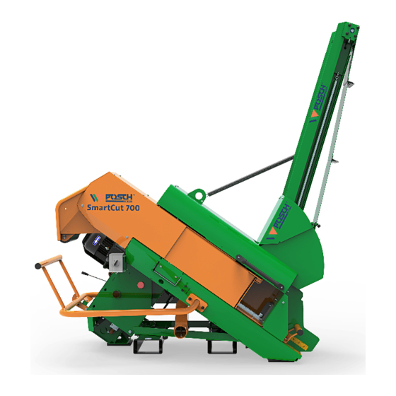
Page 12: Major Machine Components
General Major machine components Electric motor Cover - conveyor belt Ball valve Conveyor belt Log carriage Control box Oil tank Switchgear box Oil filter Frame Rating plate Three-point linkage connection Protective cover Drive – PTO shaft Sensor start system Switch/plug Log stop Rope winch - conveyor belt Lifting eye... -
Page 13: Stickers And Their Meaning
General Stickers and their meaning Only operate with all guards and protective equipment in place Do not open or remove guards or protective equipment while the machine is in operation Caution, tool runs on Only carry out repair, set-up, maintenance and cleaning work when the drive is switched off and the tool is stationary. - Page 14 General Make sure the rope is wound onto the winch correctly! Cut length 50 52 Lifting point for forklift Z2001311 Maximum saw blade diameter max 700 mm min 690 mm 30 mm Z2001340 Oil level Z2001360 Max. angle of conveyor belt Z2001441 The universal joint shaft must be removed before opening the protective cover.
-
Page 15: Set-Up
General Stickers on belt conveyor Danger zone Z2001162 Lubrication point Z2050400 Set-up Ensure the machine is stable before starting it. Set up the machine on a level, firm and clear work surface. The machine must be placed directly on the ground. Do not place wooden boards, flat pieces of metal etc. -
Page 16: Start-Up
Start-up Start-up Check the machine for potential damage prior to every use. ▪ When doing so, pay particular attention to inspection activities in section "Checks [➙ 34]". Before starting to operate the machine, please check that the protective and safety systems are working and also the hydraulic hoses and oil level. -
Page 17: Type Z
Start-up Note the rotation direction of the electric motor (see arrow on motor). If the motor is rotating in the wrong direction: A phase inverter in the plug controls the direction of rotation of the motor (press in the disc in the plug with a screwdriver and turn 180˚). -
Page 18: Electric Motor Or Universal Joint Shaft Drives
Start-up Supply voltage 12 V 16 A Continuous current Remember to unplug the continuous current plug at the end of work, otherwise the tractor battery may be drained. If you do not have a 3-pole continuous current connection on the tractor, a secure supply direct from the battery is required. -
Page 19: Operation
Operation Operation In order to ensure optimal operation of the sensor system, the machine should be run at idling speed for at least 3 minutes. At outdoor temperatures below 0°C, let the machine idle for approximately five minutes to allow the hydraulic system to reach the correct operating temperature (the hydraulic pipes will then be warm to the touch). - Page 20 Operation Crank – Rope winch (F15 and F4) Conveyor belt Fixing chain (F15 and F4) Conveyor belt trough Hole for mounting the chain (F15 and Control lever - raise/lower conveyor belt (F5) Conveyor belt types Conveyor belt type Conveyor belt length Conveyor height Belt width 150 cm...
- Page 21 Operation Transport position: ▪ Crank the conveyor belt fully upwards using the rope winch. ▪ Attach the safety chain on the conveyor belt. Conveyor belt - Type F4 Working position: It is vital to lower the conveyor belt before start-up, otherwise the conveyor belt will be damaged.
- Page 22 Operation Conveyor belt - Type F5 Working position: It is vital to lower the conveyor belt before start-up, otherwise the conveyor belt will be damaged. ▪ Lower the conveyor belt using the control lever (Conveyor belt - raise/lower). See ..Conveyor belt (option F5) [➙ 23] ▪...
- Page 23 Operation Main control Log carriage – automatic mode not working (excess pressure) In automatic mode the log carriage waits for it to be filled with logs and then automatically runs the cutting procedure. When the last log has been processed, the log carriage remains standing in the start position.
- Page 24 Operation 5.1.3 Log stop Locking screw Indicator Fixing plate with clamping lever Scale Log stop The log length can be adjusted with the stop to a length of 18, 20, 25, 27, 30, 33, 35, 40, 45, 50, 52 cm. ▪...
- Page 25 Operation Wood length up to 33 cm: ▪ Lift the detent lever, move the sliding element right out and allow the detent lever to re- engage. – The transfer hatch is activated (to prevent congestion). Wood length longer than 33 cm: ▪...
- Page 26 Operation Switchgear box Switchgear box Switch – Emergency mode (on the top of the box in the case of the Type Z) The switch for emergency mode (permanent movement of the log carriage) is located under the switchgear box. Off: Sensor mode On: Emergency mode (illuminated) ▪...
- Page 27 Operation Object not recognised Object recognised Display – Switching state is not illuminated is illuminated Display – Contamination is not illuminated is illuminated heavy contamination: Display – Switching state is not illuminated is not illuminated Display – Contamination is not illuminated is not illuminated Influence of extraneous light: If extraneous light (sunlight, flashlight, etc.) hits the sensor, the automatic function of the log...
-
Page 28: Work Operation
Operation Work operation Only one person may operate the machine at a time. Ensure that no other people are in the vicinity of the machine. 5.2.1 Sawing ▪ Move the conveyer belt to the working position. See ..Conveyor belt [➙ 19] ▪... - Page 29 Operation See ..Setting sensor [➙ 39] Note regarding the fault: When rectifying a possible fault, it is vital to switch off the drive and secure it so it cannot be switched on accidentally or started-up by unauthorised persons.
-
Page 30: Put Out Of Operation
Put out of operation Put out of operation Before switching off the machine, depressurise all hydraulic functions. Position all controls in neutral or switch these off. Put drives out of operation Driven by electric motor (Type E) Type E11 ▪ Press the red button. ▪... -
Page 31: Transport
Transport Transport Before transportation, it is vital that the drive is switched off and secured to ensure that it cannot be switched on accidentally or started up by unauthorised persons. Disconnect the machine from the mains. ▪ In addition, pull out the plug of the device. ▪... -
Page 32: Lifting With A Crane
Transport In order to test the overall stability, the following formula can be used to calculate the minimum weight on the front side I with a minimum front axle load of 20% of the empty F,min weight of the tractor: c + d F x b 0,2 x... - Page 33 Transport When using a crane, only lift the machine by the lifting eyes. Only lifting gear with the permitted load capacity may be used.
-
Page 34: Checks
Checks Checks Before control work is carried out on the machine, it is vital that the drive is switched off and secured to ensure that it cannot be switched on accidentally or started up by unauthorised persons. Disconnect the machine from the mains. ▪... -
Page 35: Hydraulic Lines
Checks Work on electrical equipment must only be carried out by qualified electricians. Hydraulic lines After the first hour of operation, check that all hydraulic connections are secure and are not leaking. Check that all hydraulic connections are secure and are not leaking after every further 100 hours of operation. - Page 36 Checks Note regarding the hydraulic oil level The conveyor belt must always be retracted. See ..Conveyor belt [➙ 19] 8.7.2 Transmission oil level Oil inlet screw Oil drain screw Oil level screw If the oil seeps out of the hole of the oil level screw when the machine is on level ground, the maximum oil level has been reached.
-
Page 37: Maintenance
Work on electrical equipment must only be carried out by qualified electricians. Never work without the protective guards in place. Only use original - POSCH - spare parts. Lubrication Dispose of oily and greasy parts and oil residues in accordance with legal regulations. -
Page 38: Saw Blade
Multi-purpose grease 5028 Saw blade Always wear protective gloves when handling saw blades. Only strengthened POSCH saw blades may be used. Standard saw blades are too weak and pose a safety risk. Observe the maximum saw blade speed specified by the manufacturer. -
Page 39: Setting Sensor
Maintenance Recommended saw blade Item no. Diameter Hole Teeth Type Z1300101 700 mm 30 mm Carbide (widia) Only saw blades conforming to the EN 847-1 standard may be used. Safety of the saw blade In accordance with the EN 1870-6 standard, the saw blade is secured with Aluminium inserts. -
Page 40: Changing The V-Belt
Maintenance Teach button Connector (rotating) LED - Switching state display The switching state of the sensor can be set by pressing the Teach button. In doing so, it should be noted that the use of sharp objects (needle, tweezers, etc.) may damage the rubber seal over the button. - Page 41 Maintenance V-belt types Machine type Belt Number (pcs.) Item no. XPA 1357 Lw Z1940118 ZE11 XPA 1357 Lw / XPA 3 / 3 Z1940118 / 1500 Lw Z1940200 9.4.2 Changing the V-belts on a Z-drive Front V-belt guard plate Transmission Side V-belt guard plate Lock nut –...
-
Page 42: Oil Changing
Maintenance 9.4.3 Changing the V-belts on a ZE-drive Hexagon bolt – motor plate Lock nut - tensioning screw Motor plate Tensioning screw ▪ Remove the V-belt guard plates. See ..Changing the V-belts on a Z-drive [➙ 41] ▪ Loosen the four hexagon bolts on the motor plate (two front, two rear). ▪... - Page 43 Maintenance Vent screw Oil sight glass Oil drain screw ▪ Remove the ventilation screw. ▪ Open the oil drain screw. The oil drain screw is located on the base of the oil tank. ▪ Drain the old hydraulic oil into a container. ▪...
- Page 44 Maintenance Manufacturer Oil specification ESSO Univis N46 CASTROL Hyspin AWH-M 46 ARAL Vitam VF46 GENOL Hydraulic oil 520 FUCHS Plantohyd 32S * / Renolin B46 HVI *..biological hydraulic oils 9.5.2 Oil filter Filter cover Filter insert The filter insert should be changed every time the oil is changed. Any aluminium particles can be disregarded, as these occur when the pump is running in.
-
Page 45: Conveyor Belt
Maintenance Total filling capacity 0.7 litres Note regarding the transmission oil change Thanks to the space-saving and compact design, filling the transmission oil is a little more difficult to complete. This is best done using a filling funnel and an extension hose. Recommended transmission oils Manufacturer Oil specification... - Page 46 Maintenance ▪ In addition, pull out the plug of the device. ▪ Disengage the universal joint shaft on the tractor. – Before disengaging, turn the manual throttle to minimum. ▪ Remove the universal joint shaft from the tractor. Clean the machine regularly to ensure proper operation. Only wash new machines (during the first 3 months) with a sponge.
-
Page 47: Additional Equipment
Additional equipment Additional equipment 10.1 Hour meter (PTO drive) Button – "Info" Display – PTO shaft speed Display – Operating hours Display - Battery voltage Function: The rotation speed is shown on the display as soon as the machine is operational. Pressing the "Info"... -
Page 48: Troubleshooting
Troubleshooting Troubleshooting Before rectifying faults on the machine, it is vital that the drive is switched off and secured to ensure that it cannot be switched on accidentally or started up by unauthorised persons. Disconnect the machine from the mains. ▪... -
Page 49: Disposal
Troubleshooting 11.1 Disposal Disposal must be carried out in accordance with the relevant national applicable regulations and/or guidelines. Dispose of recyclable materials separately ensuring they are clean for recycling. -
Page 50: Technical Data
Technical data Technical data Type ZE11 Drive Drive type PTO/Electric motor Output 15 / 11 S6 ** Voltage Fusing Motor speed 1455 PTO shaft speed Saw blade Saw blade diameter Min. log diameter Max. log diameter Noise Sound pressure level dB(A) Dimensions * Width... -
Page 51: Service
Service Service POSCH- Product To order spare parts for your machine please contact your local dealer directly. If you require a replacement parts list for your machine, you can download this at any time by entering the serial number at the following link:... -
Page 52: Ec Declaration Of Conformity
Below is the name and address of the signatory to the above EC Declaration of Conformity, who is authorised to compile the technical documentation. Leibnitz, date: Posch 02.09.2013 Gesellschaft m. b. H. Paul-Anton-Kellerstrasse 40 8430 Leibnitz, Austria Ing. - Page 56 Your Posch-Dealer...
Need help?
Do you have a question about the SmartCut 700 Comfort - Z and is the answer not in the manual?
Questions and answers