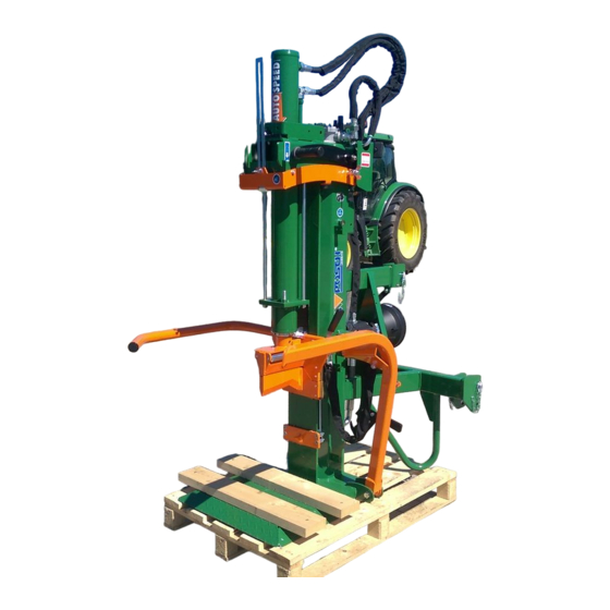
Posch HydroCombi 18 Operating Instructions Manual
Hide thumbs
Also See for HydroCombi 18:
- Operating instructions manual (48 pages) ,
- Operating instructions manual (52 pages)

Related Manuals for Posch HydroCombi 18


Summary of Contents for Posch HydroCombi 18
- Page 1 Operating Instructions HydroCombi 18 D1010209 - Edition - 1001 *D1010209-1001* English Copyright by Posch Gesellschaft m.b.H., Made in Austria...
- Page 2 Machine number:................Serial number:..................POSCH Austria: 8430 Leibnitz, Paul-Anton-Keller-Strasse 40, telephone: +43 (0) 3452/82954, fax: +43 (0) 3452/82954-53, e-mail: leibnitz@posch.com POSCH Germany: 84149 Velden/Vils, Preysingallee 19, telephone: +49 (0) 8742/2081, fax: +49 (0) 8742/2083, e-mail: velden@posch.com...
-
Page 3: Table Of Contents
Contents Contents Foreword Copyright notice Liability for defects Reservations Definitions Operating instructions Safety information Explanation of symbols General safety information Safety instructions for log splitter Safety instructions for rope winches Noise Remaining risks Proper use General Scope Description The most important components of the machine Labels and their meanings Set-up Start-up... - Page 4 Contents Protective guards Screw fittings Hydraulic lines Tool guide Oil level Two-hand controller Log retaining tip Maintenance Tool guide Oil changing Cleaning Special equipment 10.1 Greater wood length (V) 10.2 Rope winch 10.3 Tractor travel gear 10.4 Road travel gear Additional equipment 11.1 Splitting cross...
-
Page 5: Foreword
Foreword Foreword Thank you for buying our product. This machine has been built in conformity with applicable European standards and regulations. These operating instructions explain how to operate the machine safely and efficiently and how to maintain it. Any person entrusted with the transport, installation, commissioning, operation or maintenance of the machine must have read and understood: ▪... -
Page 6: Operating Instructions
Foreword The operating personnel (operators) are those entrusted by the operator to operate the machine. Technical personnel Technical personnel are persons entrusted by the operator of the machine with special tasks such as installation, set-up, maintenance and troubleshooting. Electrician An electrician is a person who, by virtue of his specialist training, has knowledge of electrical systems, standards and regulations and is able to identify and prevent possible hazards. -
Page 7: Safety Information
Safety information Safety information Explanation of symbols The following symbols and instructions warn against possible injuries or damage to property or are intended to assist you in your work. DANGER Hazard warning This symbol appears next to instructions relating to safety at work wherever a hazard to life and limb exists if the instructions are not complied with. -
Page 8: General Safety Information
Never leave the machine running unattended. Switch off the machine's drive unit before carrying out any adjustments. Only use original - POSCH - spare parts. Do not modify or tamper with the machine. Work on electrical equipment must only be carried out by qualified electricians. -
Page 9: Safety Instructions For Rope Winches
It is up to the operating personnel to ensure that work is carried out safely. Proper use The machine - HydroCombi 18 - is designed exclusively for splitting logs with a diameter of 10 - 80 cm and a length of 10 - 110 cm. -
Page 10: General
Hour counter for machines with PTO drive Description The machine HydroCombi 18 is designed exclusively for splitting logs with a maximum length of 10 - 110 cm. The splitter is driven hydraulically; the hydraulic system is driven by the tractor's hydraulic system or by an electric motor or by a PTO shaft. -
Page 11: The Most Important Components Of The Machine
General The log is placed on a pressure plate under the splitting blade. During operation the splitting blade moves down into the log and splits it. The most important components of the machine Cylinder Oil drain screw Guide rod Three-point linkage Ventilation screw PTO pump Shut-off rod... -
Page 12: Labels And Their Meanings
General Labels and their meanings Only work alone. Do not carry out any repair, set-up, maintenance or cleaning work unless the drive unit is switched off and the tool is at rest. Wear protective gloves. Wear safety shoes. Wear goggles and ear protection. Caution, moving parts. -
Page 13: Set-Up
General Oil level Maximum PTO speed Direction of PTO or motor rotation Phase inverter Set-up Ensure the machine is stable before starting it. Set up the machine on a level, firm and clear work surface. The machine must be placed directly on the ground. Do not place wooden boards, flat pieces of metal etc. -
Page 14: Start-Up
Start-up Start-up Check the safety equipment, hydraulic hoses and oil level before start-up. Driven by electric motor (type E) 4.1.1 Machines with 400 V motor The machine must only be operated on a 30 mA FI fault current protection circuit. Work on electrical equipment must only be carried out by qualified electricians. -
Page 15: Driven By Tractor Via Cardan Shaft (Type Pzg)
Start-up Driven by tractor via cardan shaft (type PZG) 1. Assemble the machine on the three-point linkage of the tractor. 2. Attach the universal joint shaft and secure with the safety chain. 3. Clockwise rotation of the tractor PTO shaft. 4. - Page 16 Start-up 5. Slowly engage the tractor PTO shaft and allow the machine to start moving. 6. Set the required PTO speed using the manual throttle. Maximum PTO speed: ▪ 380 rpm The maximum PTO speed must on no account be exceeded, otherwise the oil will become too hot.
-
Page 17: Operation
Operation Operation At outdoor temperatures below 0°C, let the machine idle for approximately five minutes to allow the hydraulic system to reach the correct operating temperature (the hydraulic pipes will then be warm to the touch). "Autospeed" "Autospeed" enables pressure-controlled switching between the two feed speeds. ▪... -
Page 18: Extending The Cylinder
Operation Extending the cylinder Hexagon nut The machine is supplied with the cylinder in the lowered position. Before starting work, the cylinder must be extended and fixed. When raising and lowering the cylinder, make sure the hydraulic hoses are not trapped. 1. - Page 19 Operation Shut-off rod Guard bracket 1. Place the log vertically under the splitting blade and press it against the retaining tip, so that even a thin log stands up by itself. 2. When you press both control levers down simultaneously, the splitting blade moves down and splits the log.
-
Page 20: Lifting Device
Operation 5.3.1 Notes on splitting Never split logs that are cut at an angle. Logs must always be split lengthways. To split very deformed wood: ▪ split the billets from the edge. Remove jammed wood from the splitting blade with a striking tool. Lifting device Lifting arm Lifting chain... - Page 21 Operation The logs which are to be split are lifted into the splitting position using the retracting splitting blade of the lifting device. Only use the lifting device if the machine is mounted on the three-point linkage or is secured with the support bracket to prevent it from tipping over.
-
Page 22: Switching Off The Machine
Switching off the machine Switching off the machine Before switching off the machine, depressurise all hydraulic functions by placing all control levers in the neutral position. Driven by electric motor (Type E) Move the switch to the 0 position. Driven by tractor via universal joint shaft (type PZG, PZ) Disengage the universal joint shaft on the tractor. -
Page 23: Transport
Transport Transport The cylinder must be lowered before transporting the machine. To lower the cylinder for transport: Hexagon nut ▪ Press the control levers downwards. Extend the splitting blade fully. ▪ Loosen the 2 hexagon nuts of the cylinder on the cylinder support plate. Stow the two hexagon nuts on the right hand side of the shut-off flap (secure with wing nuts). - Page 24 Transport Crank up the jockey wheel. Check tyre pressure - max 3.5 bar. Observe the road traffic regulations when driving on public highways. Maximum transport speed: 6 km/h (10 km/h) - Observe local regulations. When the machine is uncoupled from the tractor, it must be placed on a firm, level surface.
-
Page 25: Checks
Checks Checks Before carrying out any checks on the machine, the drive unit MUST be switched off! Disconnect the machine from the mains. Protective guards All the protective guards (covers, safety grilles, etc.) must be in place. Screw fittings Tighten all screws and nuts after the first hour of operation. Tighten the screws and nuts after every 100 hours of operation. -
Page 26: Log Retaining Tip
Checks Check that the rocker moves freely. Log retaining tip Log retaining tip If the end of the log retaining tip breaks off, it can easily be reground with an angle-grinder. -
Page 27: Maintenance
Disconnect the machine from the mains. Work on electrical equipment must only be carried out by qualified electricians. Never work without the protective guards in place. Only use original - POSCH - spare parts. Tool guide Grease nipple Grease brush Lubricate the grease nipple on the tool guide with lubricating grease every 10 hours. - Page 28 Maintenance ▪ Drain the old hydraulic oil into a container. ▪ Screw the oil drain screw back into the tank and fill with new hydraulic oil. ▪ Turn on the machine and allow it to run for a short while. ▪...
-
Page 29: Cleaning
Maintenance Cleaning Before carrying out any cleaning work on the machine, the drive unit MUST be switched off! Disconnect the machine from the mains. Clean the machine regularly to ensure proper operation. Only wash new machines (during the first 3 months) with a sponge. ▪... -
Page 30: Special Equipment
Special equipment Special equipment 10.1 Greater wood length (V) Model for logs up to 130 cm length. 10.2 Rope winch Lowering arm Control lever Gripper Control valve The rope winch may only be used when the machine is connected to the three-point linkage of the tractor! The hydraulic rope winch enables heavy logs to be pulled across to the machine without any physical effort. - Page 31 Special equipment 10.2.1 Manual rope winch Pull rope in Release or extend rope Operation: 1. Press the control lever briefly to position 2. – The rope is released. 2. Pick up the log hook or grabber and pull the rope over to the log. 3.
- Page 32 Special equipment 10.2.2.1 Transmitter Button 1 Emergency stop Button 2 Charging socket The radio transmitter includes controls for actuating the various functions. The emergency stop function must be deactivated before you can start using the transmitter. ▪ This can be done by simultaneously pressing and holding both send buttons for around 5 sec.
-
Page 33: Tractor Travel Gear
Special equipment 10.2.2.3 Faults on the radio control Fault Cause Remedy No response when Emergency stop function is Press both transmitter switching on the active buttons at the same time for transmitter approx. 5 seconds No electricity supply available Charge rechargeable battery/ use charged battery Undervoltage warning on Rechargeable battery is not... -
Page 34: Road Travel Gear
Special equipment – Undo the clip pins, push the brake bolts outwards towards the wheels and secure again. ▪ Place the whole travel gear with the machine in a vertical position. – To do this, grip the towbar by the retainer and swing it upwards. Transport position: ▪... - Page 35 Special equipment Locking lever Lower three-point bolt ▪ Unlock the two locking levers on the lower three-point bolts and swing them upwards. ▪ Raise the travel gear by the towbar until it is released from the lower three-point bolts. ▪ Move the travel gear away, pulling it forwards.
-
Page 36: Additional Equipment
Additional equipment Additional equipment 11.1 Splitting cross Splitting cross Splitting blade Locking clip During the splitting process the log is split into four billets. For uniform billets with maximum log diameter of 30-35 cm. Not suitable for knotty or deformed wood (danger of jamming). Fitting: 1. -
Page 37: Splitting Table
Additional equipment During the splitting process the log is split into two parts. Rollers on the splitting blade prevent the split log from getting caught during the return movement. Fitting: 1. Extend the splitting blade approx. 30 cm and switch off the machine. 2. -
Page 38: Push-Fit Floor Grate
Additional equipment Fit the upper Stauff clamp. Fit the angle joint to the shut-off at the top. Place the splitting table on the base plate. When fitting the splitting table, be careful not to put your head under the splitting blade or injure your head on the splitting blade. -
Page 39: Troubleshooting
Troubleshooting Troubleshooting Fault Possible cause Remedy See page Electric motor fails to Faulty power supply Have the cable See [➙ 14] start or switches off cable examined by a frequently specialist Fuses keep tripping - Use correctly-rated incorrectly rated fuse for fuses power supply cable Motor circuit breaker... -
Page 40: Technical Data
Technical data Technical data Type Drive Drive type Tractor hydraulics PTO shaft Electric motor Power 14.3 14.3 Voltage Fuse Motor speed 1440 PTO speed Splitting system Splitting force Cylinder stroke Max. pressure Max. log length Max. log diameter Forward speed cm/s 15.2 16.5... -
Page 41: Service
Service Service POSCH product To order spare parts for your machine please contact your local dealer directly. -
Page 42: Ec Declaration Of Conformity
EC Electromagnetic Compatibility (EMC) Directive 89/336/EEC. This Declaration is not valid for any modifications to the machine which are not approved by us. Log splitter - HydroCombi 18 Item no.: M6190 , M6192 , M6194 , M6196 , M6198 Serial no.:... - Page 44 Your Posch-Dealer...
Need help?
Do you have a question about the HydroCombi 18 and is the answer not in the manual?
Questions and answers