
Related Manuals for Posch SplitMaster 30


Summary of Contents for Posch SplitMaster 30
- Page 1 Operating Instructions SplitMaster 30 D1010419 - V001 *D1010419-V001* English Copyright by Posch Gesellschaft m.b.H., Made in Austria...
- Page 2 Machine number:................Serial number:..................POSCH Austria: 8430 Leibnitz, Paul-Anton-Keller-Strasse 40, telephone: +43 (0) 3452/82954, fax: +43 (0) 3452/82954-53, e-mail: leibnitz@posch.com POSCH Germany: 84149 Velden/Vils, Preysingallee 19, telephone: +49 (0) 8742/2081, fax: +49 (0) 8742/2083, e-mail: velden@posch.com...
-
Page 3: Table Of Contents
Contents Contents Foreword Copyright notice Liability for defects Reservations Definitions Operating instructions Safety information Explanation of symbols General safety information Safety instructions for log splitter Safety instructions for rope winches Noise Remaining risks Proper use Incorrect use General Scope Description The most important components of the machine Stickers and their meaning Set-up... - Page 4 Contents Transport Transportation using the travel gear Checks Protective guards Screw fittings Electrical equipment Hydraulic lines Tool guide Two-hand controller Oil level Maintenance Tool guide Oil changing Diesel engine Cleaning Special equipment 10.1 Radio remote control 10.2 Rope winch Additional equipment 11.1 Splitting blade variants Troubleshooting...
-
Page 5: Foreword
Foreword Foreword Thank you for buying our product. This machine has been built in conformity with applicable European standards and regulations. These operating instructions explain how to operate the machine safely and efficiently and how to maintain it. Any person entrusted with the transport, installation, commissioning, operation or maintenance of the machine must have read and understood: ▪... -
Page 6: Operating Instructions
Foreword The operating personnel (operators) are those entrusted by the operator to operate the machine. Technical personnel Technical personnel are persons entrusted by the operator of the machine with special tasks such as installation, set-up, maintenance and troubleshooting. Electrician An electrician is a person who, by virtue of his specialist training, has knowledge of electrical systems, standards and regulations and is able to identify and prevent possible hazards. -
Page 7: Safety Information
Safety information Safety information Explanation of symbols The following symbols and instructions in this manual provide warnings about possible personal injury or property damage or give useful information about working with the machine. DANGER Warning about danger zones Instruction regarding safe working, where non-compliance entails the risk of serious or fatal injury. -
Page 8: General Safety Information
Never leave the machine running unattended. Switch off the machine's drive unit before carrying out any adjustments. Only use original - POSCH - spare parts. Do not modify or tamper with the machine. Work on electrical equipment must only be carried out by qualified electricians. -
Page 9: Safety Instructions For Rope Winches
Safety information ▪ This may mean that the machine operator is required to leave the place of operation while the wood feed is loaded, in order to comply with the necessary safety distances. Do not hold the log with your hand while splitting. Do not reach into the splitting area. -
Page 10: Proper Use
It is up to the operating personnel to ensure that work is carried out safely. Proper use The machine - SplitMaster 30 - is designed exclusively for splitting logs with a diameter of 10 - 80 cm and a length of 50 - 125 cm. -
Page 11: General
F0002024 8-billet splitting blade F0002179 Hour counter for machines with electric motor F0001806 Hour counter for machines with PTO drive Description The SplitMaster 30 machine is suitable solely for splitting logs with a maximum length of 50 - 125 cm. -
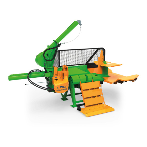
Page 12: The Most Important Components Of The Machine
General The cylinder stroke can be adjusted to shorter logs. The "Autospeed" function ensures a very high splitting speed. The splitter is driven hydraulically; the hydraulic system is either driven by an electric motor, a PTO shaft or by a diesel engine. The machine is operated via a two-hand safety controller. -
Page 13: Stickers And Their Meaning
General Stickers and their meaning Only one person may operate the machine at a time Only carry out repair, set-up, maintenance and cleaning work when the drive is switched off and the tool is stationary. Wear protective gloves Wear safety shoes Wear goggles and ear defenders Caution, moving tools Always read the user manual before operating the machine... -
Page 14: Set-Up
General Safety lock - lifting device Z200 1328 Oil level Z2001360 Phase inverter Z205 0010 Fuel: Diesel Lubrication point Z2050400 Stickers on controls Operation - lifting device and knife adjustment Z205 0865 Operation - splitter Stickers on travel gear Tyre pressure max. -
Page 15: Start-Up
Start-up Start-up Before starting to operate the machine, please check that the protective and safety systems are working and also the hydraulic hoses and oil level. Before each start-up, the condition of the electrical cables must be checked. If a fault occurs during operation, the machine must be shut down immediately and secured so it cannot be switched on accidentally or started-up by unauthorised persons. - Page 16 Start-up Neutral position Delta position Star position If the electric motor will not start (red light for rotational direction detection is on): A phase inverter in the plug controls the direction of rotation of the motor (press in the disc in the plug with a screwdriver and turn 180˚).
-
Page 17: Driven By Tractor Via Cardan Shaft (Type Z)
Start-up Neutral position Delta position Star position If the electric motor will not start (red light for rotational direction detection is on): Procedure as for type 1. Driven by tractor via cardan shaft (type Z) ▪ Attach the universal joint shaft and secure with the safety chain. ▪... -
Page 18: Powered By Diesel Engine (Type D)
Start-up Powered by diesel engine (Type D) Check the oil level before starting the engine. The procedure for starting the diesel engine is described in the engine operating instructions. Type D22 Engine information: Engine Fuel Consumption approx. Hatz 2L41C Diesel 3 –... -
Page 19: Operation
Operation Operation At outdoor temperatures below 0°C, let the machine idle for approximately five minutes to allow the hydraulic system to reach the correct operating temperature (the hydraulic pipes will then be warm to the touch). "Autospeed" "Autospeed" enables pressure-controlled switching between the two feed speeds. ▪... -
Page 20: Splitting Blade - Hydraulic Height Adjustment
Operation Splitting blade - hydraulic height adjustment Position Function If the control lever is pressed to the left, the spitting blade will move up. If the control lever is pressed to the right, the spitting blade will move down. This enables the splitting blade to be set in the optimum position for the timber diameter. Lifting device Lifting device Securing wedge... - Page 21 Operation ▪ Lower the lifting device by hand until it is held by the lifting cylinder. ▪ Pull the control lever for the lifting device until the lifting device moves downwards. Transport position: ▪ Press the control lever, the lifting device swings upwards. ▪...
-
Page 22: Cylinder
Operation Cylinder Spring flap Control lever Closure component Cylinder flange Pusher Timber support Working position: The machine is supplied with the cylinder in the retracted position. Before starting work, the cylinder must be extended and fixed. ▪ Swing the spring flap away and pull the closure component out. ▪... -
Page 23: Setting The Splitting Distance (Stroke)
Operation ▪ Extend the pusher as far as it will go. ▪ Remove the closure component from the base, fit it to the pusher and secure in position with the flap. ▪ Push both control levers away from you in order to retract the pressure plate. When extending and retracting the cylinder, make sure the hydraulic hoses are not trapped! ▪... -
Page 24: Timber Support
Operation ▪ Turn off the machine. – See:Switching off the machine [➙ 28] ▪ Pull out the spring pin and move the shut-off rod to the desired position. ▪ Then secure the shut-off rod again with the spring pin. The splitting stroke is defined using the following lengths: Position Log length 1st position... - Page 25 Operation ▪ Fully lower the lifting device. ▪ Place the log on the lifting device and raise it. – The log automatically rolls into the splitting trough. without second split: ▪ Fully lower the lifting device. Align the splitting blade. ▪...
-
Page 26: Changing The Splitting Blade
Operation ▪ Lower the lifting device until you feel a slight jolt in the control lever (the arrow on the lifting device is aligned with the arrow on the sticker). ▪ Adjust the height of the splitting knife such that, always starting from the underside, the log can be split in layers. - Page 27 Operation ▪ Fix the shackle supplied to the splitting blade. ▪ Secure the lifting gear to the shackle. Only lifting gear with the permitted load capacity may be used. ▪ Pull the splitting blade out by lifting it up (using a crane, front loader, etc.). 5.8.1 Repository for splitting blades Splitting blade...
-
Page 28: Put Out Of Operation
Put out of operation Put out of operation Before switching off the machine, depressurise all hydraulic functions by placing all control levers in the neutral position. Switching off the machine Driven by electric motor (Type E) Type E7.5 ▪ Move the switch to the 0 position. ▪... -
Page 29: Transport
Transport Transport Before transport, it is vital to switch off the drive and secure it so it cannot be switched on accidentally or started-up by unauthorised persons. Disconnect the machine from the mains. ▪ In addition, pull out the plug of the device. ▪... - Page 30 Transport ▪ Check tyre pressure - max 3.5 bar. Observe the road traffic regulations when driving on public highways. Maximum transport speed: 80 km/h When the machine is uncoupled from the tractor, it must be placed on a firm, level surface.
-
Page 31: Checks
Checks Checks Before control work on the machine, it is vital to switch off the drive and secure it so it cannot be switched on accidentally or started-up by unauthorised persons. Disconnect the machine from the mains. ▪ In addition, pull out the plug of the device. ▪... -
Page 32: Hydraulic Lines
Checks Hydraulic lines After the first hour of operation, check that all hydraulic connections are secure and are not leaking. Check that all hydraulic connections are secure and are not leaking after every further 100 hours of operation. ▪ Damaged hydraulic lines must be replaced immediately. Tool guide The tool guide must always be well greased. -
Page 33: Maintenance
▪ Remove the universal joint shaft from the tractor. Work on electrical equipment must only be carried out by qualified electricians. Never work without the protective guards in place. Only use original - POSCH - spare parts. Tool guide Grease nipple Grease brush Lubricate the grease nipple on the tool guide with lubricating grease every 10 hours. - Page 34 Maintenance Ventilation screw Oil drain screw Oil sight glass ▪ Retract the pusher before changing the oil. ▪ Remove the ventilation screw. ▪ Open the oil drain screw. The oil drain screw is located on the base of the oil tank. ▪...
-
Page 35: Diesel Engine
Maintenance 9.2.2 Oil filter Filter cover Filter insert The filter insert should be changed every time the oil is changed. Any aluminium particles can be disregarded, as these occur when the pump is running in. Do not wash out the filter insert with petrol or paraffin products, as these damage it. Diesel engine For maintenance operations, refer to the engine operating instructions. -
Page 36: Special Equipment
Special equipment Special equipment 10.1 Radio remote control A radio-controlled machine is considerably easier to operate. Radio control is used to wirelessly operate the rope winch. Safety information Familiarise yourself with the system before using radio control! Only authorised persons who have received relevant training are permitted to operate the machine with radio control! You should always check that the emergency stop switch is working correctly before starting to use the machine. - Page 37 Special equipment Using the transmitter As well as the function buttons, the rotary safety button must also always be used. Button Position Function Splitting cylinder Extend pusher (split) Lifting device Raise Lifting device Lower Adjust blade Raising the splitting blade Adjust blade Lower splitting blade Splitting cylinder...
-
Page 38: Rope Winch
Special equipment Colour Function yellow Receiver has a power supply Transmitter is switched off green Transmitter is switched on (signals are being received) green Channel (function) being actuated 10.1.3 Faults on the radio control Fault Cause Rectification No response when Emergency stop function is Press both transmitter switching on the... - Page 39 Special equipment The rope winch with 1000 kg traction may only be used when the machine is connected to the three-point linkage of the tractor. On the tractor chassis, the rope winch with 500 kg traction must be used. The operator must always stand at a higher level than the log that is drawn in! No one may stand in the area where the rope winch reels in the rope! There must always be a clear view of the whole length of rope even when fully unrolled! On both sides of the winch, the reel-in angle of the rope must not be greater than 40°!
- Page 40 Special equipment Take care when using radio control. Choose a safe location from where you can clearly see the entire work area. Never leave a transmitter switched on and unattended! In the event of a fault, the radio control system must be shut down immediately. ▪...
- Page 41 Special equipment Supply voltage 12 V 16 A Continuous current Remember to unplug the continuous current plug at the end of work, otherwise the tractor battery may be drained. The receiver is now ready for operation. The minimum voltage must be 11.2 V under load (radio-controlled rope winch activated), otherwise soft start will not function.
- Page 42 Special equipment Fault Cause Rectification The transmitter shows The receiver does not have any Switch on the light on the normal operation display, electricity supply tractor however no control There is no radio connection Check the connecting cable commands can be available to the receiver carried out...
-
Page 43: Additional Equipment
Additional equipment Additional equipment 11.1 Splitting blade variants Splitting knife, 2-section Splitting knife, 8-section Splitting knife, 6-section "Easy" splitting knife The log is split into 2, 6 or 8 pieces (billets) in one splitting process. -
Page 44: Troubleshooting
Troubleshooting Troubleshooting Before rectifying faults on the machine, it is vital to switch off the drive and secure it so it cannot be switched on accidentally or started-up by unauthorised persons. Disconnect the machine from the mains. ▪ In addition, pull out the plug of the device. ▪... -
Page 45: Disposal
Troubleshooting Hydraulic cylinder Sealing sleeve worn Renew sealing sleeves leaking Piston rod guide loose Retighten piston rod guide Piston rod damaged Renew piston rod Control lever does not Latch seat in control Turn the latch seat stay in return position valve is worn Latch seat is worn Replace latch seat... -
Page 46: Technical Data
Technical data Technical data Type PZG (S) Drive Drive type Diesel engine Output Voltage Fusing Motor speed 2100 PTO shaft speed Splitting system Splitting force 29.4 Cylinder stroke Max. pressure Max. log length Max. log diameter Advance speed cm/s Retraction speed cm/s Dimensions * Length... - Page 47 Technical data Type PZG-E15 (S) Drive Drive type PTO/Electric motor Output 37 / 15 S6 ** Voltage Fusing Motor speed 1450 PTO shaft speed Splitting system Splitting force 29.4 / 30 Cylinder stroke Max. pressure 255 / 260 Max. log length Max.
-
Page 48: Service
Service Service POSCH- Product To order spare parts for your machine please contact your local dealer directly. If you require a replacement parts list for your machine, you can download this at any time by entering the serial number at the following link: www.posch.com/download... -
Page 49: Ec Declaration Of Conformity
The machine furthermore complies with the EC Low Voltage Directive 2006/95/EC and the EC Electromagnetic Compatibility (EMC) Directive 2004/108/EC. This Declaration is not valid for any modifications to the machine which are not approved by us. Wood splitter - SplitMaster 30 Item no.: M6652, M6652S, M6662, M6667, M6667S, M6672, M6672S Serial no.:... - Page 52 Your Posch-Dealer...
Need help?
Do you have a question about the SplitMaster 30 and is the answer not in the manual?
Questions and answers