Posch HydroCombi 18 Operating Instructions Manual
Hide thumbs
Also See for HydroCombi 18:
- Operating instructions manual (44 pages) ,
- Operating instructions manual (48 pages)

Related Manuals for Posch HydroCombi 18


Summary of Contents for Posch HydroCombi 18
- Page 1 Operating Instructions HydroCombi 18 D1010493-V002 English Copyright by Posch Gesellschaft m.b. H., Made in Austria...
- Page 2 Machine number:................Serial number:..................POSCH Austria: 8430 Leibnitz, Paul-Anton-Keller-Strasse 40, telephone: +43 (0) 3452/82954, fax: +43 (0) 3452/82954-53, e-mail: leibnitz@posch.com POSCH Germany: 84149 Velden/Vils, Preysingallee 19, telephone: +49 (0) 8742/2081, fax: +49 (0) 8742/2083, e-mail: velden@posch.com D1010493-V002...
-
Page 3: Table Of Contents
English Contents Contents 1 Foreword ............................. 1.1 Copyright notice .......................... 1.2 Liability for defects ........................1.3 Reservations ..........................1.4 Definitions ........................... 1.5 Operating instructions ......................... 2 Safety information ..........................2.1 Explanation of symbols ....................... 2.2 General safety information ......................2.3 Noise ............................10 2.4 Remaining risks........................... - Page 4 Contents English 8.8 Log retaining tip........................... 30 8.9 Oil level ............................30 8.10 Rope winch ..........................31 9 Maintenance............................32 9.1 Tool guide ........................... 32 9.2 Oil changing ..........................32 9.3 Cleaning ............................34 10 Special equipment..........................35 10.1 Hydraulic lifting device ........................ 35 10.2 Rope winch ..........................
-
Page 5: Foreword
English Foreword | 1 1 Foreword Thank you for buying our product. This machine has been built in conformity with applicable European standards and regula- tions. These operating instructions explain how to operate the machine safely and efficiently and how to maintain it. Any person entrusted with the transport, installation, commissioning, operation or mainten- ance of the machine must have read and understood: •... -
Page 6: Operating Instructions
1 | Foreword English The operating personnel (operators) are those entrusted by the operator to operate the ma- chine. Technical personnel Technical personnel are persons entrusted by the operator of the machine with special tasks such as installation, set-up, maintenance and troubleshooting. Electrician An electrician is a person who, by virtue of his specialist training, has knowledge of electrical systems, standards and regulations and is able to identify and prevent possible hazards. -
Page 7: Safety Information
English Safety information | 2 2 Safety information 2.1 Explanation of symbols The following symbols and instructions in this manual provide warnings about possible per- sonal injury or property damage or give useful information about working with the machine. Warning about danger zones Instruction regarding safe working, where non-compliance entails the risk of serious or fatal injury. -
Page 8: General Safety Information
2 | Safety information English Symbol for an area where noise levels can exceed 85 dB(A). Non-observance can cause hearing problems or deafness. Wear protective gloves Wear safety shoes Instruction Symbol for proper use of the machine. Non-compliance can result in malfunctions or damage to the machine. Further information Symbol for further information relating to a bought-in part. - Page 9 Never leave the machine running unattended. Switch off the machine's drive unit before carrying out any adjustments. Only use original - POSCH - spare parts. Do not modify or tamper with the machine. Work on electrical equipment must only be carried out by qualified electricians.
-
Page 10: Noise
It is up to the operating personnel to ensure that work is carried out safely. 2.5 Proper use The machine - HydroCombi 18 - is designed exclusively for splitting logs with a diameter of 8-50 cm and a length of 55-110 cm. -
Page 11: General
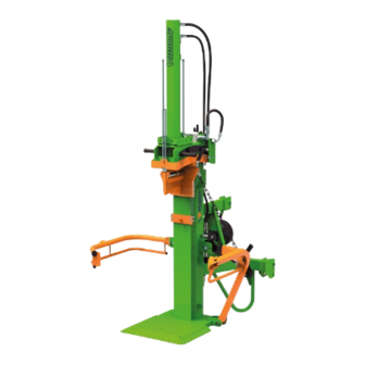
Hour counter for machines with Z motor 3.2 Description The HydroCombi 18 machine is suitable solely for splitting logs with a maximum length of 55-110 cm. The splitter is driven hydraulically; the hydraulic system is driven by the tractor's hydraulic system or by an electric motor or by a PTO shaft. -
Page 12: Major Machine Components
3 | General English The splitting knife presses into the log when working and splits it. 3.3 Major machine components Cylinder Oil drain screw Guide rod Three-point linkage Vent screw PTO pump Shut-off rod Lubrication nipple Two-hand control Rating plate Splitting knife with timber holder func- Oil sight glass tion... -
Page 13: Stickers And Their Meaning
English General | 3 3.4 Stickers and their meaning Only one person may operate the machine! Z2050200 Caution, moving tools! Only carry out repair, set-up, maintenance and cleaning work when the drive is switched off and the tool is stationary. Always read the user manual before operating the machine! Z2040010 Wear eye protection! -
Page 14: Set-Up
3 | General English Grease tool guide Z2001260 Lubrication point Z2050400 Oil level Z2001360 Phase inverter Z205 0010 Maximum efficiency max. 35 l/min Z2050540 Operation - "Fixomatic" Z2001326 Operation - splitter Stickers on travel gear Tyre pressure max. 3,5 bar Z2050330 3.5 Set-up Ensure the machine is stable before starting it. -
Page 15: Start-Up
English Start-up | 4 4 Start-up Check the machine for potential damage prior to every use. • When doing so, pay particular attention to inspection activities in section "Checks [} 29]". Before starting to operate the machine, please check that the protective and safety systems are working and also the hydraulic hoses and oil level. -
Page 16: Driven By Tractor Via Universal Joint Shaft
4 | Start-up English A tight plug connection can rip the CEE plug out of the switch housing. • This can be remedied using standard plugs and a silicone spray. Any such damage to the switch is not covered by the guarantee. 4.2 Driven by tractor via universal joint shaft Type Z •... -
Page 17: Driven By Tractor With Shaft-Mounted Pump (Type Pz)
English Start-up | 4 4.4 Driven by tractor with shaft-mounted pump (type • Assemble the machine on the three-point linkage of the tractor. • Attach the transmission to the tractor PTO shaft and secure with the chain to prevent twisting. –... -
Page 18: Operation
5 | Operation English 5 Operation At outdoor temperatures below 0°C, let the machine idle for approximately five minutes to allow the hydraulic system to reach the correct operating temperature (the hydraulic pipes will then be warm to the touch). 5.1 Controls and functions 5.1.1 "Autospeed"... - Page 19 English Operation | 5 5.1.2 Cylinder Hexagon nut Working position: The machine is supplied with the cylinder in the retracted position. Before starting work, the cylinder must be extended and fixed. When extending and retracting the cylinder, make sure the hydraulic hoses are not trapped! •...
- Page 20 5 | Operation English 5.1.3 Setting the splitting distance (stroke) Shut-off rod Wing nut The return stroke of the splitting blade can be changed using the shut-off rod. • Start the machine. See ….. Start-up [} 15] • Extend the splitting blade to around the centre. •...
- Page 21 English Operation | 5 Transport position: • Swing the guard bracket upwards. 5.1.5 Mechanical lifting device Lifting arm Lifting chain Detent lever Safety bar Mounting plate The logs which are to be split are lifted into the splitting position by means of the lifting device.
-
Page 22: The Splitting Procedure With "Fixomatic
5 | Operation English 5.2 The splitting procedure with "Fixomatic" Do not reach under the splitting tool; always grasp the log from the side. Shut-off rod Lower splitting knife section Guard bar “Fixomatic” operating lever Timber retaining tip • Place the log upright under the splitting knife. •... - Page 23 English Operation | 5 Never split angle-cut wood! Logs must always be split lengthways. Position the log to be split so that the knothole is closer to the splitting knife. Splitting extremely crooked wood: • split the billets from the edge. Remove jammed wood from the splitting blade with a striking tool.
-
Page 24: Put Out Of Operation
6 | Put out of operation English 6 Put out of operation Before switching off the machine, depressurise all hydraulic functions. Position all controls in neutral or switch these off. 6.1 "Fixomatic" Lower splitting knife section Gas spring upper splitting knife section Before switching off the machine always bring the lower splitting knife section together with the upper splitting knife section to prevent damage to the gas spring (piston rod) or its seal (rust, ice, etc.). - Page 25 English Put out of operation | 6 Driven by the tractor's hydraulic system (type PS) • Turn the control valve on the tractor to the “Off” position. • Shut down the tractor. • Remove or disconnect the hydraulic hoses from the tractor. Driven by tractor with shaft-mounted pump (type PZ) •...
-
Page 26: Transport
7 | Transport English 7 Transport Before transportation, it is vital that the drive is switched off and secured to ensure that it cannot be switched on accidentally or started up by unauthorised persons. Disconnect the machine from the power supply when it has come to a standstill: Pull out the plug of the device (mains plug). -
Page 27: Transportation Using The Chassis
English Transport | 7 (kg) Empty weight of the tractor (kg) Front axle load of the empty tractor (kg) Rear axle load of the empty tractor (kg) Total weight of the machine (kg) Total weight of the front load Distance between front load's centre of gravity and centre of the front axle *** Wheelbase of the tractor Distance between centre of the rear axle and centre of the lower link balls *** Distance between centre of the lower link balls and the machine's centre... - Page 28 7 | Transport English – Check the correct position of the ball coupling (marking: + sign or green colour or no red) and also by pulling forcefully. • Move the stabiliser foot or support wheel (depending on the chassis type) to the top posi- tion.
-
Page 29: Checks
English Checks | 8 8 Checks Before carrying out checks on the machine, it is absolutely essential to switch off the drive unit and to ensure that it cannot be switched on accidentally or started up by unauthorised persons. Disconnect the machine from the power supply when it has come to a standstill: Pull out the plug of the device (mains plug). -
Page 30: Hydraulic Lines
8 | Checks English • Where appropriate, test of the earth conductor and measurement of the earth conductor current • Where appropriate, measurement of the insulation resistance. Work on electrical equipment must only be carried out by qualified electricians. 8.4 Hydraulic lines After the first hour of operation, check that all hydraulic connections are secure and are not leaking. -
Page 31: Rope Winch
English Checks | 8 8.9.1 Hydraulic oil level When the oil sight glass is filled, the oil level is at its maximum. When the oil level is in the centre of the oil sight glass, the oil level is at its minimum. If this is the case, the hydraulic oil must be topped up immediately. -
Page 32: Maintenance
Wear protective gloves and protective shoes (safety class S3) and close-fitting work clothes during maintenance work. Work on electrical equipment must only be carried out by qualified electricians. Never work without the protective guards in place. Only use original - POSCH - spare parts. 9.1 Tool guide Lubrication nipple Grease brush Lubricate the grease nipple on the tool guide with lubricating grease every 10 hours. - Page 33 English Maintenance | 9 9.2.1 Changing the hydraulic oil The oil change should be carried out after 1000 operating hours or annually. • Retract the splitting blade before changing the oil. • Remove the ventilation screw. • Open the oil drain screw. The oil drain screw is located at the rear of the base of the column.
-
Page 34: Cleaning
9 | Maintenance English 9.2.2 Oil filter Filter cover Filter insert The filter insert should be changed every time the oil is changed. Any aluminium particles can be disregarded, as these occur when the pump is running in. Do not wash out the filter insert with petrol or paraffin products, as these damage it. 9.3 Cleaning Before cleaning work is carried out on the machine, it is vital that the drive is switched off and secured to ensure that it cannot be switched on accidentally or started up by unauthor-... -
Page 35: Special Equipment
English Special equipment | 10 10 Special equipment 10.1 Hydraulic lifting device Control lever Lifting arm Lifting cylinder The hydraulic lifting device may only be used when the machine is connected to the three- point linkage of the tractor! The hydraulic lifting device must always be in the uppermost position before commen- cing the splitting operation! When the control valve is actuated, the hydraulic lifting device lifts the logs into position for splitting. - Page 36 10 | Special equipment English 10.1.1 Operating the hydraulic lifting device Lifting arm up Lifting arm down D1010493-V002...
-
Page 37: Rope Winch
English Special equipment | 10 10.2 Rope winch Lowering arm (option) Control valve Gripper (option) Shut-off flap Safety information: The rope winch may only be used when the machine is connected to the three-point linkage of the tractor! The operator must always stand at a higher level than the log that is drawn in! No one may stand in the area where the rope winch reels in the rope! There must always be a clear view of the whole length of rope even when fully unrolled! On both sides of the winch, the reel-in angle of the rope must not be greater than 40°! - Page 38 10 | Special equipment English • Attach the log hook or grabber to the log. • Push the control lever to position 1, pull the log across to the machine and position it be- low the splitting blade. Do not retract the rope completely but leave a gap of about 5 cm to the inlet limiter - failure to do this may result in damage to the rope winch! •...
- Page 39 English Special equipment | 10 Transmitter LED red Button 2 Start Emergency stop Button 1 LED green The radio transmitter includes controls for actuating the various functions. The emergency stop function must be deactivated before you can start using the transmitter. •...
-
Page 40: Road Travel Gear
10 | Special equipment English Fault Cause Rectification No response when switch- Emergency stop function is act- Press start button ing on the transmitter Insert new batteries No electricity supply available Undervoltage warning on Batteries are low or empty Insert new batteries the transmitter (after short Batteries defective period of operation, LED... - Page 41 English Special equipment | 10 Working position: • Attach the towbar to the tractor. • Crank the two stabiliser feet downwards. • Unlock the lighting system, pull it out and place it on the side mount. • Unlock and pull out the three-point bolt on the upper three-point holder. •...
-
Page 42: Additional Equipment
11 | Additional equipment English 11 Additional equipment 11.1 Splitting table Lower Stauff clamp Hand lever Compression spring Splitting table Shut-off rod Fixing lever Upper Stauff clamp Splitting table base Angle joint Winged bolt Mounting: Fit the lower Stauff clamp. Thread the compression spring from below onto the shut-off rod, and push those parts to- gether into the lower Stauff clamp. -
Page 43: Push-Fit Floor Grate
English Additional equipment | 11 When fitting the splitting table, be careful not to put your head under the splitting blade or in- jure your head on the splitting blade. • Raise both the fixing levers, push the splitting table fully on to the frame, then lower the levers. -
Page 44: Troubleshooting
12 | Troubleshooting English 12 Troubleshooting Before rectifying faults on the machine, it is vital that the drive is switched off and secured to ensure that it cannot be switched on accidentally or started up by unauthorised persons. Disconnect the machine from the power supply when it has come to a standstill: Pull out the plug of the device (mains plug). -
Page 45: Disposal
English Troubleshooting | 12 Hydraulic cylinder leak- Sealing sleeve worn Renew sealing sleeves Piston rod guide loose Retighten piston rod guide Piston rod damaged Renew piston rod Control lever does not Latch seat in control Turn the latch seat stay in return position valve is worn Latch seat is worn Replace latch seat... -
Page 46: Technical Data
13 | Technical data English 13 Technical data Type E5.5 Drive Drive type Tractor hydraulics PTO shaft Electric motor Output 5.5 S6 ** Voltage Fusing Motor speed 1440 pto speed Splitting system Splitting force Cylinder stroke Max. pressure Max. log length Max. -
Page 47: Service
Service | 14 14 Service POSCH- Product To order spare parts or a service for your machine please contact your local dealer directly. If you require a spare parts list for your machine, you can download this at any time by entering the serial number at the following link: https://www.posch.com/en/service/download/... -
Page 48: Ec Declaration Of Conformity
What is more, the machine complies with the EC Electromagnetic Compatibility (EMC) Dir- ective 2014/30/EU. This Declaration is not valid for any modifications to the machine which are not approved by Wood splitter - HydroCombi 18 Item no.: M6190 , M6192 , M6194 , M6196 , M6198 Serial no.:... - Page 49 English Notes D1010493-V002...
- Page 50 English D1010493-V002...
- Page 51 English D1010493-V002...
- Page 52 Your Posch Dealer...
Need help?
Do you have a question about the HydroCombi 18 and is the answer not in the manual?
Questions and answers