Table of Contents
Advertisement
Quick Links
Instruction Manual MN013019EN
IZM6 Series Air Circuit Breaker Instruction Manual
Instructions apply to:
IZM61
(1) Only qualified electrical personnel should be permitted to work
on the equipment.
(2) Always de-energize primary and secondary circuits if a circuit
breaker cannot be removed to a safe work location.
(3) Drawout circuit breakers should be levered (racked) out to the
disconnect position.
(4) All circuit breakers should be switched to the off position and
mechanism springs discharged.
Failure to follow these steps for all procedures described in this
instruction leafl et could result in death, bodily injury, or property
damage.
The instructions contained in this il and on product labels have to
be followed. Observe the fi ve safety rules:
– Disconnecting;
– Ensure that devices cannot be accidentally restarted;
– Verify isolation from the supply;
– Earthing and short-circuiting; and
– Covering or providing barriers to adjacent live parts.
Disconnect the equipment from the supply. Use only authorized
spare parts in the repair of the equipment. The specifi ed mainte-
nance intervals as well as the instructions for repair and exchange
must be strictly adhered to prevent injury to personnel and dam-
age to the switchboard.
WARNING
WARNING
IZM65/67
Advertisement
Table of Contents

Subscribe to Our Youtube Channel
Related Manuals for Eaton IZM6 Series


Summary of Contents for Eaton IZM6 Series
- Page 1 Instruction Manual MN013019EN IZM6 Series Air Circuit Breaker Instruction Manual Instructions apply to: IZM61 IZM65/67 WARNING (1) Only qualified electrical personnel should be permitted to work on the equipment. (2) Always de-energize primary and secondary circuits if a circuit breaker cannot be removed to a safe work location.
- Page 2 If further information is desired by purchaser regarding particular installation, operation, or maintenance of particular equipment, contact the local Eaton office. IZM6 Series Air Circuit Breaker Instruction Manual MN013019EN March 2023 www.eaton.com.cn...
-
Page 3: Table Of Contents
IZM61/65/67 electrical wiring diagram ............56 SECTION 9: INSTALLATION, OPERATION AND MAINTENANCE NOTICE ....57 IZM6 Series Air Circuit Breaker Instruction Manual MN013019EN March 2023 www.eaton.com.cn... -
Page 4: Section 1: Circuit Breaker Overview
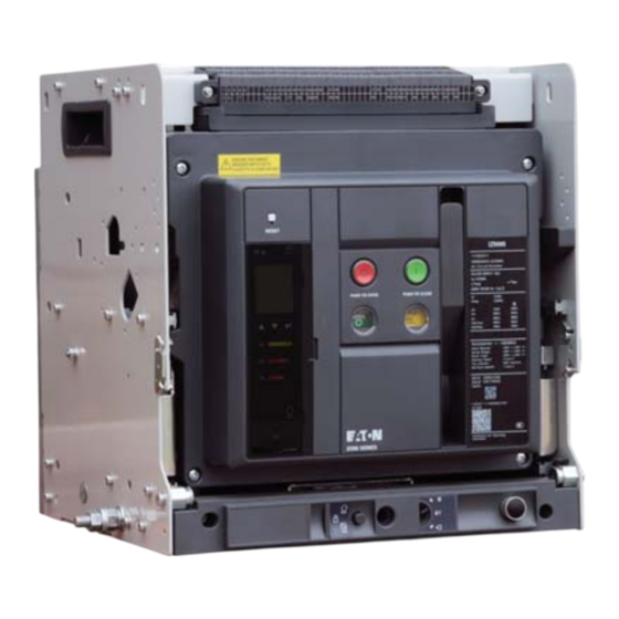
The products have passed national compulsory product certifica- tion with CCC mark. The circuit breakers feature isolation function, with the symbol as “ ”. Drawout type Fixed type IZM6 series air circuit breaker IZM6 Series Air Circuit Breaker Instruction Manual MN013019EN March 2023 www.eaton.com.cn... -
Page 5: Standards In Compliance
III for the remaining auxiliary circuits and control circuits; • The vertical inclination does not exceed 5° during mounting; • Transportation and storage temperature:-25°C - +85°C. IZM6 Series Air Circuit Breaker Instruction Manual MN013019EN March 2023 www.eaton.com.cn... -
Page 6: Section 2: Circuit Breaker Structure
Position locking device Lock catch button Three position indication Nameplate Open/Closed indication Released/Charged indication Manual charging handle Closing button Opening button Fault tripping indicator/Rest button (without dis- connecting switch) IZM6 Series Air Circuit Breaker Instruction Manual MN013019EN March 2023 www.eaton.com.cn... -
Page 7: Internal Structure: Three-Dimension Diagram
Shunt coil Under voltage release Secondary terminal Delivery handle Operating mechanism Basic device Intelligent controller Reset button Opening button Closing button Cover Auxiliary contact Closing coil Charing handle Motor operator IZM6 Series Air Circuit Breaker Instruction Manual MN013019EN March 2023 www.eaton.com.cn... -
Page 8: Section 3: Circuit Breaker Installation
Washer IZM6 GB5783- GB6170- GB97 GB93- IZM61 M10×30 Φ10 IZM65 M12×30 Φ12 IZM67 M12×30 Φ12 otes: See below diagram for detailed mounting methods and locations. Washer Hexagon head bolt IZM6 Series Air Circuit Breaker Instruction Manual MN013019EN March 2023 www.eaton.com.cn... -
Page 9: Power Loss (At Ambient Temperature Of +40°C)
The copper bar specifi cations used in the table are when the circuit breaker is at the ambient temperature of up to 40 °C and installed in an open area, in accordance with the conventional thermal conditions in GB14048.2. IZM6 Series Air Circuit Breaker Instruction Manual MN013019EN March 2023 www.eaton.com.cn... -
Page 10: Section 4: Accessory
Power loss IZM61 80VA 80VA IZM65/67 150W 150W 150W 150VA 150VA Shunt release Charging time (s) The shunt release enables the circuit breaker to open remotely. • IZM61/65/67 Auxiliary contact IZM6 Series Air Circuit Breaker Instruction Manual MN013019EN March 2023 www.eaton.com.cn... - Page 11 62 64 65 67 68 70 71 73 74 76 77 79 80 82 83 85 86 88 89 91 Conventional Rated operating Rated control thermal voltage U capacity current I Auxiliary contact AC400 800VA AC230 DC220 300W DC110 Undervoltage and Novoltage releases IZM6 Series Air Circuit Breaker Instruction Manual MN013019EN March 2023 www.eaton.com.cn...
- Page 12 The counter calculates the number of operations, which can be read on the front panel. It is compatible with manual and electri- cal operation functions. Counter Position indication position mounted inside the switch IZM6 Series Air Circuit Breaker Instruction Manual MN013019EN March 2023 www.eaton.com.cn...
- Page 13 (as shown in the figure below); 4. Lever the basic device back into the cassette, and place the circuit breaker in the Connect position; IZM6 Series Air Circuit Breaker Instruction Manual MN013019EN March 2023 www.eaton.com.cn...
-
Page 14: Section 5: Izm61/65/67 Accessory Installation
720° Circuit breaker 1 Circuit breaker 2 Figure 1. Step 1 otes: 1 = Closed, 0 = Open IZM6 Series Air Circuit Breaker Instruction Manual MN013019EN March 2023 www.eaton.com.cn... - Page 15 Step 1: Remove the mounting screws from the circuit breaker panel with the Phillips screwdriver. Pull down the charging handle (by an approx. 45° angle) to remove the cover. Screw Figure 1. Step 1 IZM6 Series Air Circuit Breaker Instruction Manual MN013019EN March 2023 www.eaton.com.cn...
- Page 16 Step 1: Remove the mounting screws from the circuit breaker panel with the Phillips screwdriver. Pull down the charging handle (by an approx. 45° angle) to remove the cover. Screw Figure 1. Step 1 IZM6 Series Air Circuit Breaker Instruction Manual MN013019EN March 2023 www.eaton.com.cn...
- Page 17 Step 1: Remove the mounting screws from the circuit breaker panel with the Phillips screwdriver. Pull down the charging handle (by an approx. 45° angle) to remove the cover. Screw Figure 1. Step 1 IZM6 Series Air Circuit Breaker Instruction Manual MN013019EN March 2023 www.eaton.com.cn...
- Page 18 Figure 4. Step 3 Figure 1. Step 2 Step 4: Connect the three conductors of the motor operator to Terminal 40, 41 and 42 respectively. Step 5: Put the cover back on. IZM6 Series Air Circuit Breaker Instruction Manual MN013019EN March 2023 www.eaton.com.cn...
- Page 19 Step 5: Finally, put the basic device back into the cassette, and measure whether the corresponding switch at the three positions can be properly switched on. Figure 1. Step 1 IZM6 Series Air Circuit Breaker Instruction Manual MN013019EN March 2023 www.eaton.com.cn...
- Page 20 Step 2: Remove the basic device after it is levered out, and remove the cover. Then, mount the pressing plate on the right side of the operating mechanism shaft (with M4×8 screws). Pressing plate Screw M4×12 Figure 1. Step 2 IZM6 Series Air Circuit Breaker Instruction Manual MN013019EN March 2023 www.eaton.com.cn...
- Page 21 Figure 3. Step 4 Step 5: Remove the screws from the arc extinguishing cover, mount the rail, and secure it with screws. Arc extinguishing cover screws Figure 4. Step 5 IZM6 Series Air Circuit Breaker Instruction Manual MN013019EN March 2023 www.eaton.com.cn...
- Page 22 Step 2: Remove the small square groove, as indicated in the fig- ure, in the cover with the knife, then put the cover back. Remove Screw M4×8 Figure 8. Step 2 Figure 11. Step 4 IZM6 Series Air Circuit Breaker Instruction Manual MN013019EN March 2023 www.eaton.com.cn...
- Page 23 62 64 65 67 68 70 71 73 74 76 77 79 80 82 83 85 86 88 89 91 Figure 1. Step 1 Figure 14. Auxiliary contact label IZM6 Series Air Circuit Breaker Instruction Manual MN013019EN March 2023 www.eaton.com.cn...
- Page 24 Whether Terminal 31 and 32 are switched on when it can be closed. Step 6: Put the motor operator and cover back separately. Pressing plate Screw M4×12 Figure 1. Step 1 IZM6 Series Air Circuit Breaker Instruction Manual MN013019EN March 2023 www.eaton.com.cn...
- Page 25 • Screws M4×20 (2) • Screws M4×8 (3) • Screw M4×12 (1) Screw M4×20 Figure 6. Step 3 Step 4: Mount the mechanical interlock onto the mounting panel with 3 screws (M4×8). IZM6 Series Air Circuit Breaker Instruction Manual MN013019EN March 2023 www.eaton.com.cn...
- Page 26 Circuit breaker A can be closed after Circuit Breaker B or C is opened. • Among Circuit Breaker A, B and C, only one or two circuit breakers can be closed. IZM6 Series Air Circuit Breaker Instruction Manual MN013019EN March 2023 www.eaton.com.cn...
- Page 27 Step 1: Remove the mounting screws from the circuit breaker panel with the Phillips screwdriver. Pull down the charging handle (by an approx. 45° angle) to remove the cover. Screw Figure 1. Step 1 IZM6 Series Air Circuit Breaker Instruction Manual MN013019EN March 2023 www.eaton.com.cn...
- Page 28 Step 1: Remove the mounting screws from the circuit breaker panel with the Phillips screwdriver. Pull down the charging handle (by an approx. 45° angle) to remove the cover. Screw Figure 1. Step 1 IZM6 Series Air Circuit Breaker Instruction Manual MN013019EN March 2023 www.eaton.com.cn...
- Page 29 Step 1: Remove the mounting screws from the circuit breaker panel with the Phillips screwdriver. Pull down the charging handle (by an approx. 45° angle) to remove the cover. Screw Figure 1. Step 1 IZM6 Series Air Circuit Breaker Instruction Manual MN013019EN March 2023 www.eaton.com.cn...
- Page 30 Elastic washer Figure 4. Step 3 Step 4: Connect the three conductors of the motor operator to Terminal 40, 41 and 42 respectively. Step 5: Put the cover back on. IZM6 Series Air Circuit Breaker Instruction Manual MN013019EN March 2023 www.eaton.com.cn...
- Page 31 Step 5: Finally, put the basic device into the cassette, and mea- 0.3A 250VDC sure whether the corresponding switch at the three positions can be properly switched on. Figure 3. Step 2: Label IZM6 Series Air Circuit Breaker Instruction Manual MN013019EN March 2023 www.eaton.com.cn...
- Page 32 Screw Cutout area Figure 4. Step 6 Step 7: Put the cover back. Figure 1. Step 1 IZM6 Series Air Circuit Breaker Instruction Manual MN013019EN March 2023 www.eaton.com.cn...
- Page 33 Step 1: Remove the mounting screws from the circuit breaker panel with the Phillips screwdriver. Pull down the charging handle (by an approx. 45° angle) to remove the cover. Screw Figure 1. Step 1 IZM6 Series Air Circuit Breaker Instruction Manual MN013019EN March 2023 www.eaton.com.cn...
- Page 34 Then, mount the pressing plate on the right side of the operating mechanism shaft (with M5×12 screws). Pressing plate M5×12 Figure 5. Step 6 Figure 1. Step 2 IZM6 Series Air Circuit Breaker Instruction Manual MN013019EN March 2023 www.eaton.com.cn...
- Page 35 Step 2: Remove the small square groove, as indicated in the fig- ure, in the cover with the knife, then put the cover back. Remove Figure 8. Step 2 IZM6 Series Air Circuit Breaker Instruction Manual MN013019EN March 2023 www.eaton.com.cn...
- Page 36 Step 1: Remove the mounting screws from the circuit breaker panel with the Phillips screwdriver. Pull down the charging handle (by an approx. 45° angle) to remove the cover. Screw Figure 1. Step 1 IZM6 Series Air Circuit Breaker Instruction Manual MN013019EN March 2023 www.eaton.com.cn...
- Page 37 Phillips screwdriver. Pull down the charging handle (by an approx. 45° angle) to remove the cover. otes: The padlock is prepared by customers themselves. Screw Figure 1. Step 1 IZM6 Series Air Circuit Breaker Instruction Manual MN013019EN March 2023 www.eaton.com.cn...
- Page 38 Step 6: Put the motor operator and cover back separately. cover. Mount the pressing plate on the right side of the operating mechanism and secure it with the M5×12 screw. Pressing plate Screw M5×12 Figure 1. Step 1 IZM6 Series Air Circuit Breaker Instruction Manual MN013019EN March 2023 www.eaton.com.cn...
- Page 39 Step 1: Remove the cover, mount the pressing plate on the right side of the operating mechanism with the M5×12 screw. Pressing plate M5×12 Figure 4. Step 1 IZM6 Series Air Circuit Breaker Instruction Manual MN013019EN March 2023 www.eaton.com.cn...
-
Page 40: Section 6: Circuit Breaker Operation
Circuit breaker A can be closed after Circuit Breaker B or C is opened. • Among Circuit Breaker A, B and C, only one or two circuit breakers can be closed. Press IZM6 Series Air Circuit Breaker Instruction Manual MN013019EN March 2023 www.eaton.com.cn... -
Page 41: Lever-In Operation Of Drawout Circuit Breaker
3. Push the circuit breaker’s basic device inward until you hear two “clicks”, which means that the basic device reaches the “Disconnected” position, and the “sliding plate’s locking device” locks the basic device. IZM6 Series Air Circuit Breaker Instruction Manual MN013019EN March 2023 www.eaton.com.cn... -
Page 42: Lever-Out Operation Of Drawout Circuit Breaker
"unlock button" will be ejected. At this point, the circuit breaker has fully reached the mounting position, so you can no longer continue to turn the crank handle clockwise. IZM6 Series Air Circuit Breaker Instruction Manual MN013019EN March 2023 www.eaton.com.cn... -
Page 43: Drawout Circuit Breaker Position Locking
2. Put the padlock through. At this point, the basic device cannot switch positions. Pull rod Lock diameter 6mm optimum CAUTION Remove the crank handle from the position switch hole before pulling out the position lock’s pull rod. IZM6 Series Air Circuit Breaker Instruction Manual MN013019EN March 2023 www.eaton.com.cn... -
Page 44: Section 7: Outline And Mounting Dimension Diagrams
Disconnected position Outside of the door 2xØ5 Current 200-1250A 1600A Dimension B (mm) 131.5 Door escutcheon cutout CB bottom CB bottom 11×Ø5 11×Ø5 CB center CB center Cutout center IZM6 Series Air Circuit Breaker Instruction Manual MN013019EN March 2023 www.eaton.com.cn... - Page 45 Outside of the door 2xØ11 Current 200-1250A 1600A Dimension B (mm) 13.5 13.5 87.5 Door escutheon cutout CB bottom CB bottom CB center 10×Ø5 Cutout center CB center 10×Ø5 IZM6 Series Air Circuit Breaker Instruction Manual MN013019EN March 2023 www.eaton.com.cn...
- Page 46 Standard type Current 400-1600A 2000-2500A Dimension B (mm) Door escutheon cutout 327.2 327.2 57.5 CB bottom CB bottom CB center CB center Cutout center 11×Ø5 11×Ø5 185.2 185.2 185.2 185.2 IZM6 Series Air Circuit Breaker Instruction Manual MN013019EN March 2023 www.eaton.com.cn...
- Page 47 Standard type Current 400-1600A 2000-2500A Dimension B (mm) Door escutheon cutout 327.2 327.2 57.5 CB bottom CB bottom CB center CB center Cutout center 8×Ø5 8×Ø5 185.2 185.2 185.2 185.2 IZM6 Series Air Circuit Breaker Instruction Manual MN013019EN March 2023 www.eaton.com.cn...
- Page 48 Section 7: Outline and mounting dimension diagrams Drawout type(IZM67 2000-3200A) Front view Vertical wiring 277.5 162.5 4xØ13 4x(13x23) 4xØ13 4x(23x13) Disconnected position Outside of the door 3×Ø13 12.5 Standard type IZM6 Series Air Circuit Breaker Instruction Manual MN013019EN March 2023 www.eaton.com.cn...
- Page 49 Outside of the door 3×Ø13 Standard type Door escutheon cutout 327.2 327.2 57.5 CB bottom CB bottom CB center CB center Cutout center 11×Ø5 11×Ø5 185.2 185.2 185.2 185.2 IZM6 Series Air Circuit Breaker Instruction Manual MN013019EN March 2023 www.eaton.com.cn...
- Page 50 Section 7: Outline and mounting dimension diagrams Drawout type(IZM67 4000A) Front view Vertical wiring 277.5 162.5 4xØ13 4xØ13 4x(13x23) 4x(13x23) Disconnected position Outside of the door 4xØ13 166.5 IZM6 Series Air Circuit Breaker Instruction Manual MN013019EN March 2023 www.eaton.com.cn...
- Page 51 Disconnected position Outside of the door 4xØ13 Door escutheon cutout 327.2 327.2 57.5 CB bottom CB bottom CB center CB center Cutout center 11×Ø5 11×Ø5 185.2 185.2 185.2 185.2 IZM6 Series Air Circuit Breaker Instruction Manual MN013019EN March 2023 www.eaton.com.cn...
- Page 52 Section 7: Outline and mounting dimension diagrams Fixed type (IZM67 2000-3200A) Front view Vertical wiring 2x(11x43) 2x(11x43) Ø11 Ø11 Distance when removing the arc chamber Outside of the door 3×Ø13 12.5 Standard type 122.7 IZM6 Series Air Circuit Breaker Instruction Manual MN013019EN March 2023 www.eaton.com.cn...
- Page 53 Outside of the door 3×Ø13 Standard type 122.7 Door escutheon cutout 327.2 327.2 57.5 CB bottom CB bottom CB center CB center Cutout center 8×Ø5 8×Ø5 185.2 185.2 185.2 185.2 IZM6 Series Air Circuit Breaker Instruction Manual MN013019EN March 2023 www.eaton.com.cn...
- Page 54 Section 7: Outline and mounting dimension diagrams Fixed type (IZM67 4000A) Front view Vertical wiring 58.2 2x(11x43) 2x(11x43) Ø11 Ø11 Distance when removing Outside of the door the arc chamber 4×Ø13 81.5 176.2 IZM6 Series Air Circuit Breaker Instruction Manual MN013019EN March 2023 www.eaton.com.cn...
- Page 55 Outside of the door the arc chamber 81.5 4×Ø13 176.2 Door escutheon cutout 327.2 327.2 57.5 CB bottom CB bottom CB center Cutout center CB center 8×Ø5 8×Ø5 185.2 185.2 185.2 185.2 IZM6 Series Air Circuit Breaker Instruction Manual MN013019EN March 2023 www.eaton.com.cn...
-
Page 56: Section 8: Electrical Wiring Diagrams
Position cell switch electrical wiring diagram 62 64 65 67 68 70 71 73 74 76 77 79 80 82 83 85 86 88 89 91 Connect Test Disconnected IZM6 Series Air Circuit Breaker Instruction Manual MN013019EN March 2023 www.eaton.com.cn... -
Page 57: Section 9: Installation, Operation And Maintenance Notice
"Charged". After a "click" sound is heard, the charging is done. The circuit breaker can only be put into operation after testing with the above steps to prove normal operations!!! IZM6 Series Air Circuit Breaker Instruction Manual MN013019EN March 2023 www.eaton.com.cn... - Page 58 Check whether the circuit of the under voltage release is energized Anti-closing lock is locked in the “OFF” position Unlock the anti-closing lock The circuit breaker is interlocked Remove the interlocking IZM6 Series Air Circuit Breaker Instruction Manual MN013019EN March 2023 www.eaton.com.cn...
- Page 59 THE PARTIES. • The following physical access ports are supported by the IZM6 In no event will Eaton be responsible to the purchaser or user in device: contract, in tort (including negligence), strict liability, or otherwise •...
Need help?
Do you have a question about the IZM6 Series and is the answer not in the manual?
Questions and answers