Table of Contents
Advertisement
Quick Links
Advertisement
Table of Contents
Troubleshooting

Related Manuals for Canon Oce Arizona 1200 Series


Summary of Contents for Canon Oce Arizona 1200 Series
- Page 1 Operation guide Océ Arizona 1200 Series User Manual...
- Page 2 Copyright library Copyright Copyright 2016, 2019 Océ. Illustrations and specifications do not necessarily apply to products and services offered in each local market. No part of this publication may be reproduced, copied, adapted or transmitted, transcribed, stored in a retrieval system, or translated into any language or computer language in any form or by any means, electronic, mechanical, optical, chemical, manual, or otherwise, without the prior written permission of Océ.
-
Page 3: Table Of Contents
Contents Contents Chapter 1 Introduction.........................7 Preface ................................8 Printer Specifications............................. 10 Chapter 2 Product Compliance......................11 Product Compliance............................12 Chapter 3 Safety Information......................15 Safety and Environment Information......................16 Flush................................26 UV Curing System ............................27 Safety Interlock System..........................28 Safety Awareness............................29 Roll Media Safety Awareness........................37 Chapter 4 How to Navigate the User Interface................ - Page 4 Contents Chapter 6 Operating the Océ Arizona 1200 XT................83 Océ Arizona 1200 XT Features........................84 How to Use the Océ Arizona 1200 XT Vacuum System................85 How to Print With Dual Origins........................87 Chapter 7 Roll Media Option......................89 Hardware.................................90 Specifications..............................92 Foot Pedal Switch Functions.........................
- Page 5 Contents Chapter 11 Troubleshooting......................165 Troubleshooting Overview.......................... 166 Chapter 12 Printer Maintenance....................... 167 Maintenance Guidelines..........................168 Maintenance Procedures..........................169 Check Printhead Nozzle Performance....................169 Manual Printhead Maintenance......................171 Recover Nozzles by (Optional) AMS.....................175 Cleaning the Automatic Maintenance System (AMS) ............... 176 Clean Horizontal Surfaces........................178 Clean Carriage Underside........................
- Page 6 Contents Océ Arizona 1200 Series...
-
Page 7: Chapter 1 Introduction
Chapter 1 Introduction... -
Page 8: Preface
Preface Preface Introduction This manual provides the operator with information about the following Océ Arizona 1200 Series UV flatbed inkjet printers: • Océ Arizona 1240 GT • Océ Arizona 1240 XT • Océ Arizona 1260 GT • Océ Arizona 1260 XT •... - Page 9 Preface trained operator may perform routine maintenance, the best maintenance results from familiarity with the printer's internal operation and history. Responsibilities of the Service Technician Field service technicians must have Océ service training. The service technician is responsible for all repairs, upgrading and modification requested by the customer or mandated by the Océ Service and Support Group.
-
Page 10: Printer Specifications
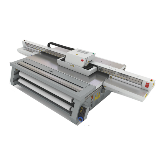
Printer Specifications Printer Specifications Introduction Your Océ Arizona 1200 Series printer is capable of producing large format images on various rigid and flexible media. The printers consist of a flatbed vacuum table and moving gantry. Media is held flat and stationary on the vacuum table during printing. The gantry contains a carriage that sweeps across the table as the gantry moves in steps along the length of the table to print an image on the media. -
Page 11: Chapter 2 Product Compliance
Chapter 2 Product Compliance... -
Page 12: Product Compliance
Product Compliance Product Compliance CE Declaration of Conformity Chapter 2 - Product Compliance Océ Arizona 1200 Series... - Page 13 Product Compliance Marking Declaration Table China Pollution Act Toxic and Hazardous Substances or Elements in the Product Part Name Lead (Pb) Mercury Cadmium Hexavalent Polybromi‐ Polybromi‐ (Hg) (Cd) Chromi‐ ated bi‐ nated dipe‐ num (CrVI) phenyls nylether (PBB) (PBDE) UV Curing Lamp Inkjet Heads O: indicates that the content of the toxic and hazardous substance in all the homogeneous...
- Page 14 Product Compliance Chapter 2 - Product Compliance Océ Arizona 1200 Series...
-
Page 15: Chapter 3 Safety Information
Chapter 3 Safety Information... -
Page 16: Safety And Environment Information
Safety and Environment Information Safety and Environment Information Important Safety and Environment User Information Before using Your printing system, make sure that it is properly installed and that You have read and understand the User Documentation in order to operate the system safely and in accordance with its functional offerings. - Page 17 Safety and Environment Information Safety and Environment Information and operating instructions. You may download the actual "http://downloads.oce.com/" Safety Data Sheets from the support site of your product at • The machine bears the CE-mark to show conformance with applicable legal requirements. The relevant CE Declaration of Conformity is part of the User Documentation.
- Page 18 Safety and Environment Information The following labels are used in the machine to identify and categorize the level of the seriousness of hazard: Label Type Description WARNING General warning sign. WARNING Risk of electric shock. Hazardous electrical parts inside. Do not remove cover. CAUTION Hot part or hot surface.
- Page 19 Safety and Environment Information Label Type Description WARNING 1. Warning: Hot surface. Take care to avoid contact with a hot surface. Optical radiation emission Category 2 2. Warning: Optical radiation. (EN 12198) Take care to avoid injury to eyes and skin when in the vicinity of optical radiation.
- Page 20 Safety and Environment Information IMPORTANT • Consult your authorized service representative before you connect other equipment to the same power outlet. • Do not connect the machine to a mains voltage or frequency which differs from the value stated on the power marking label. NOTE •...
- Page 21 Safety and Environment Information Installation WARNING • The machine may only be transported, assembled, installed and repaired by an authorized service representative. • The installation of accessories and options not permitted for the machines may constitute a violation of the Safety Regulations and Directives, and may also damage the machine. •...
- Page 22 Safety and Environment Information CAUTION • This equipment is not suitable for use in locations where children are likely to be present. • The printing system may not be operated by persons under the influence of alcohol or drugs, or by persons taking certain types of medication, such as psychotropic drugs. Disassemble and modification WARNING •...
- Page 23 Safety and Environment Information Actions in response to troubles WARNING • Immediately turn OFF the power switch and unplug the power cord from the power outlet when a piece of metal, water or any other similar foreign matter gets inside the machine. Then call your authorized service representative.
- Page 24 Safety and Environment Information UV ink CAUTION • UV inks and flush liquids can be harmful if not properly handled. Follow always the Safety Data Sheets (SDS) guidelines carefully in order to ensure maximum safety. • Avoid skin contact with ink and uncured printed media. •...
- Page 25 Safety and Environment Information UV light (UV lamps) CAUTION • Be aware that UV light is an invisible risk for eyes and skin. Superficial eye damage and burning of skin can occur with even brief exposure to UV light. Serious injuries can result from prolonged exposure, especially if unshielded.
-
Page 26: Flush
Flush Flush Flush Care and Storage A small bottle (125ml) is supplied with the printer accessory kit. Use it only to hold flush. Tip: before you begin printhead swabbing or cleaning the AMS, fill the bottle and place several swabs into it so they are soaked in flush and ready to use. -
Page 27: Uv Curing System
UV Curing System UV Curing System Introduction Lamp Replacement Replace both lamp bulbs after 500 hours of use to help ensure that the ink on prints is fully cured. Personal Safety CAUTION Warning for Seated Individuals: UV emissions are highest at a height of 90 cm (35 inches) above the floor and increase significantly the closer you are to the lamp. -
Page 28: Safety Interlock System
Safety Interlock System Safety Interlock System Introduction The printer has three Emergency-Stop buttons. The Maintenance Station drawer is part of the safety interlock system. A beacon light indicates the status of the safety system and the printer. Components of the Interlock System Emergency Stop Buttons: These are located on the Operator Control Station, and on each end of the Gantry. -
Page 29: Safety Awareness
Safety Awareness Safety Awareness Introduction This section contains two sets of principles that must be followed to assure maximum safety when operating your Océ Arizona printer. The first set uses negative examples to show you things to avoid in order to prevent injury to the operator. The second set of principles illustrates some of the residual risks that are inherent in the operation of the printer. - Page 30 Safety Awareness Avoid these Situations For Your Personal Safety Do not push or force the gantry to move manually if it is already in motion. If you do move the gan- try, a Motion Error mes- sage will display and you will have to use the mouse to click Reset on the user interface LCD...
- Page 31 Safety Awareness Avoid these Situations For Your Personal Safety Movement of the car- riage up and down may be a crush hazard. Do not rest your hands in this area during daily print- head maintenance as this process causes the car- riage to move up and down.
- Page 32 Safety Awareness Avoid these Situations For Your Personal Safety Avoid printing at a height greater than measured as this causes excessive emissions of UV light and ink mist. Keep a distance of at least 1 m (3 ft.) to the UV light when printing.
- Page 33 Safety Awareness Residual Risk Area Hazard A crushing hazard is cre- ated by the movement of the carriage along gantry rails. Keep hands away from this area unless the printer power is off. [9] Carriage Guard and Gantry Rails A high risk crushing/ pinch hazard is created by the table and the gan- try.
- Page 34 Safety Awareness Residual Risk Area Hazard A high risk crushing/ pinch hazard is created by the carriage and the gantry when the Z-Axis is moving (carriage moves up or down). [12] Carriage Vertical Movement Pinch Hazard A high risk shearing haz- ard is created by the gan- try and the gantry rail.
- Page 35 Safety Awareness Residual Risk Area Hazard A high risk shearing haz- ard is created by the gan- try and the gantry rail. This photo shows anoth- er view from the bottom. Do not place fingers or hands in this area. [14] Gantry Shear Hazard A high risk shearing haz- ard is created by the car-...
- Page 36 Safety Awareness Residual Risk Area Hazard Entanglement hazard A medium risk of finger or material entanglement is created by the web as- sembly (IGUS track). [16] IGUS Impact Hazard A medium risk impact hazard is created by the carriage when cycling from left to right.
-
Page 37: Roll Media Safety Awareness
Roll Media Safety Awareness Roll Media Safety Awareness Introduction This section contains two sets of principles that must be followed to assure maximum safety when operating the Roll Media Option (RMO) for your Arizona printer. The first image uses a negative example to show you a situation to avoid in order to prevent injury to the operator. - Page 38 Roll Media Safety Awareness RMO Residual Risks Crushing/Shear Hazard Do not place your hand near the shaft drive mo- tors when the printer is printing or when the dual foot controls are pressed. Do not place your hand on the Media Roll motor enclosure when the green beacon light is On as the gantry may move...
-
Page 39: How To Navigate The User Interface
Chapter 4 How to Navigate the User Interface... -
Page 40: Operator Interface Hardware
Operator Interface Hardware Operator Interface Hardware Introduction The Operator interacts with printer components to print, maintain, and monitor the state of the printer. This section identifies and explains the functions of the hardware. [19] Printer Hardware Operator Interface Components Hardware Interface Components Component Function 1) Main Power Switch... - Page 41 Operator Interface Hardware Component Function 8) Print Button Starts the current print job. 9) Maintenance Station Designated area for cleaning the printheads and the underside of the carriage. 10) Vacuum Zone Control Five vacuum zone control handles determine if vacuum zones 2 to Handles (image 2) 6 on the printer table are active when the vacuum pump is switch- 10) on image 1 shows op-...
-
Page 42: Printer Interface Software
Printer Interface Software Printer Interface Software Introduction The printer software is displayed on the LCD monitor. The interface has seven main modules that are accessed by tabs located at the bottom of the display. Click on these tabs to access the modules. - Page 43 Printer Interface Software Component Function Maintenance Displays maintenance tasks you must perform and indicates when to (Maintenance tab) do them. After you perform each task, the printer will record that the task was completed and then calculate when the task must be per- formed again.
-
Page 44: Print Job Control Module
Print Job Control Module Print Job Control Module Introduction Print Job Control is the first module displayed when the printer software is loaded. From this module you can manage all aspects of working with print jobs and also control many features of the printer. - Page 45 Print Job Control Module Component Function 7) Job Placement Displays the selected print job with a preview that shows the place- Preview ment of that job on the printer. 8) Archived Jobs Displays a list of all archived print jobs (they will remain in the list until deleted).
- Page 46 Print Job Control Module Command Toolbar Icons Explained Print job This command can do the following actions depending on context: • Activates a selected inactive job by moving it to the active list. • Un-holds a held job. • Un-holds an job that had an error currently. Hold job The command can do following actions depending on context: •...
- Page 47 Print Job Control Module Roll enable Enables or disables the Roll Media Option print queue (this allows you check media parameters before the job actually prints). Roll media print jobs will not print unless this icon is selected. NOTE Roll media print jobs do not require user actions to start the print job once Roll module is initialized (see Roll Media Manager in the RMO) If this icon is selected, and the job status is not on Hold, roll media print jobs will start automatically when the printer re-...
- Page 48 Print Job Control Module Move Gantry Moves the gantry from its parked position to the center of the table. Start This icon can be used to start a flatbed print job (same function as the physical button on the table). Nozzle check This icon populates the active job list with a job that prints a nozzle check pattern.
- Page 49 Print Job Control Module 7) Job Placement Preview The table placement preview shows the print location and a proportional representation of the image in relation to the table. The zoom button in the bottom right corner activates a popup preview window. If a preview image is not available, an appropriately sized white box is used as a placeholder, and the zoom button is not displayed.
- Page 50 Print Job Control Module Print Parame‐ Displays information about the print job that is currently selected: ters • Copies - use the mouse to increase or decrease. • Print Mode - Print modes are selected in THRIVE or ProductionHouse. See "Print Modes Explained"...
- Page 51 Print Job Control Module each swath with these media. Quality-Matte resolves this issue. This mode is only available when using the optional six color ink configuration (CMYKcm), which includes Light Cyan and Light Magenta inks . NOTE Some Quality print modes are also interchangeable at the printer UI. For example, if Quality mode is specified in the submitted job, Quality-Matte or Quality-Density modes may be selected in the Print Job module of the printer UI.
-
Page 52: Maintenance Tasks
Maintenance Tasks Maintenance Tasks Introduction Regular maintenance is very important to ensure the best image quality from your printer. In order to help you remember and maintain the proper schedule, the Maintenance Tasks module provides a list of the important tasks you must perform and indicates when you must do them. After you perform each task, click the Done button and the printer will record that the task was completed and then calculate when the task must be performed again. -
Page 53: Counters Module
Counters Module Counters Module Introduction The Counters module displays counters that are of interest to the operator. It shows counters for each color of ink and the total ink used. Some of the counters can be reset. Counters Component - function table Counters Explained Component Function... -
Page 54: Settings Module
Settings Module Settings Module Introduction The Settings Module allows you to review and change the date and time, network connection settings, user interface configurations, printer settings and, if installed, the Roll Media settings. Date and Time Settings • Date - display only, cannot change the date •... - Page 55 Settings Module NOTE A network name for the printer cannot consist of numeric characters only - it must be a mix of alpha-numeric characters. If the Printer name is changed, the printer must be restarted for the change to take effect. If any settings require a printer restart, a reminder will be displayed when that settings is selected.
- Page 56 Settings Module • Full carriage travel • Blank space skipping • Automatic warm-up days and time • Weekly Maintenance Day • Weekly Maintenance Time Roll Module Top Margin Specifies the distance to be left not printed above the image. Bottom Margin Specifies the distance to be left not printed below the image.
-
Page 57: Tools And Utilities Module
Tools and Utilities Module Tools and Utilities Module Introduction The Tools and Utilities Module has three sub-modules: Special Prints, Shutdown, and the System Logs. When you click on the Tools tab, Special Prints always appears first. Click on the other icons to access the sub-modules. - Page 58 Tools and Utilities Module The list on the top shows all active jobs that are currently in the print queue. Add a special print from the bottom to make it active in the Print Job Control module. If you remove a job from this list, it is also removed from the Active job list and is not available to print.
-
Page 59: Software Update Module
Software Update Module Software Update Module Introduction As we are committed to improve and refine the quality and functionality of the Océ Arizona 1200 Series printer, there will be periodic upgrades to the underlying firmware and printer software. Software updates are available only to customers with a service contract. Your local service representative will either install the upgrade or provide you with the upgrade file in some circumstances. - Page 60 Software Update Module Chapter 4 - How to Navigate the User Interface Océ Arizona 1200 Series...
-
Page 61: How To Operate Your Océ Arizona Printer
Chapter 5 How to Operate Your Océ Arizona Printer... -
Page 62: Training Requirements
Training Requirements Training Requirements Introduction The operator must receive training for safety issues, printer operation, and the appropriate ONYX Workflow software (ProductionHouse® or THRIVE) prior to operating the printer. Safety Training Before operating the Océ Arizona 1200 Series printer, make sure you have read and understood all of Chapter 3 "Safety Guidelines". -
Page 63: How To Power On And Off
How to Power ON and Off How to Power ON and Off Introduction It is critical for the printer to remain powered ON at all times. Power is required in periods of inactivity so the printer can perform automatic functions to maintain its operating state. If these functions do not take place, damage to critical components can occur. -
Page 64: How To Set Up A Print Job
How to Set Up a Print Job How to Set Up a Print Job Introduction This section explains the basic steps to set up a print job. Prepare a Digital Image with ProductionHouse or Postershop Operator must be trained to use ProductionHouse or THRIVE. Training is provided by ONYX. Print The Job From Onyx ProductionHouse When the job is sent from the ONYX software, the job transmission progress is indicated in the lower right corner of the User Interface display. - Page 65 How to Set Up a Print Job Place the media on the table in the orientation that matches the job to printed and register the media to the print origin. In the next section there are more details on how to perform the following actions.
-
Page 66: Managing The Table Vacuum
Managing the Table Vacuum Managing the Table Vacuum The Table Vacuum System Introduction The printer uses vacuum to secure media to the printer table. The table is divided up into multiple vacuum zones. Manual valves are used to activate or shut down the vacuum zones. In order for the system to work effectively, all the vacuum table holes must be covered. - Page 67 The Table Vacuum System Masking the Vacuum Table If your media does not cover all of a vacuum zone you must mask the area around the media to eliminate vacuum loss. Use scrap media or material that is equal to or less than the thickness of the media to mask the table.
-
Page 68: Using Vacuum Zones - Metric Zones
Using Vacuum Zones - Metric Zones Using Vacuum Zones - Metric Zones Introduction When the printer is shipped, the vacuum zones are configured to support either common metric or imperial media sizes . The purpose of the vacuum zones is to reduce the preprint setup time by reducing the need to mask the open area on the vacuum table when printing on the most common size media. - Page 69 Print the Metric Zone Map 3. With no media present, print the zone map directly onto the printer table. [26] Vacuum Zones Metric - GT Chapter 5 - How to Operate Your Océ Arizona Printer Océ Arizona 1200 Series...
-
Page 70: Imperial Vacuum Zones
Imperial Vacuum Zones Imperial Vacuum Zones The following shows the media dimensions that are available with the recommended Imperial vacuum zones. The name of the zone indicates which vacuum handle controls that zone. The maximum supported media size for the imperial version of the vacuum table is 48 inches x 96 inches. -
Page 71: Print Imperial Zone Map
Print Imperial Zone Map Print Imperial Zone Map A map of the vacuum zone can be printed on the table to help with the position of media over the zones. A default map is provided, but you can also create your own map, if desired. Procedure 1. -
Page 72: Batch Mode Printing
Batch Mode Printing Batch Mode Printing Introduction Batch mode printing is available for streamlining multi-layered jobs for specialty applications or facilitating set collation of multiple images on one piece of media. Individual print jobs are sent from the RIP to the printer, and then combined on the printer to create a batch job for flatbed printing. - Page 73 Batch Mode Printing 2. Select the Create Batch icon to open the batch editor. [29] Create a Batch Job 3. Provide a name for the batch job in the Batch name: field. 4. Select the Batch type: either Composite or Collation 5.
- Page 74 Batch Mode Printing 7. When the images are arranged the way you want them, click on the Back button to return to the Print Job module and automatically add the Batch job to the Active job list. NOTE You can click on the + to the left of the name of a batch job in the Active Job list to see the images it contains.
-
Page 75: Step And Repeat Printing
Step and Repeat Printing Step and Repeat Printing Introduction Step and Repeat Printing allows the operator to define a grid and place an image in each cell to print multiple copies. The operator selects the number of rows and columns desired and the number of copies needed and the copies of the image are positioned in each cell of the grid. - Page 76 Step and Repeat Printing 3. Fill in the Rows and Columns fields by either clicking on the upward pointing triangle or within the field to use the virtual keypad that appears. NOTE You can also click on the Fill area... button to have the grid created automatically based on the dimensions of the image, the size of the media, and the number of copies.
-
Page 77: Managing Media
Managing Media Managing Media How to Handle Media Introduction Océ has conducted extensive testing of many media. Since your printer is capable of imaging on a wide range of material, we encourage you to explore various media so that you can establish your own criteria for achieving high quality images in your work environment. - Page 78 How to Handle Media NOTE Dirty media can affect image quality and reliability of printer output. If you wipe the media with a tack cloth before printing, it will reduce dust and debris buildup on the carriage underside. The tack cloth removes static and also removes dust and debris that tend to attract stray ink drops. Tack cloths are used by auto-body shops to clean cars before painting.
-
Page 79: Media Registration
Media Registration Media Registration Introduction Media can be registered on the table using the built-in registration pins and the table rulers. The registration pins can be linked to the vacuum switch or activated manually by the operator to allow quick registration of the media to the printer origin. The rulers are printed on the table and provide a horizontal and vertical rule that originate from the 0,0 print origin point on the table. - Page 80 Media Registration [30] Settings for a GT Printer Setting Registration Pin Behavior for XT Printers You can set the behavior of the XT registration pins and also determine which of the pins are active in the Settings tab. The media registration pins behaviors for an XT include: •...
- Page 81 Media Registration 3. If pin behavior is set to manual – the user is allowed to activate pins using the table vacuum pedals. However, if the gantry is within safety zone of any of the pin groups, that group will ignore request to extend.
- Page 82 Media Registration Chapter 5 - How to Operate Your Océ Arizona Printer Océ Arizona 1200 Series...
-
Page 83: Operating The Océ Arizona 1200 Xt
Chapter 6 Operating the Océ Arizona 1200 XT... -
Page 84: Océ Arizona 1200 Xt Features
Océ Arizona 1200 XT Features Océ Arizona 1200 XT Features Introduction The Océ Arizona 1200 XT printer has a larger table and two vacuum pumps. These pumps provide vacuum for the vacuum zones. Any unique features of the Océ Arizona 1200 XT are documented in this chapter. -
Page 85: How To Use The Océ Arizona 1200 Xt Vacuum System
How to Use the Océ Arizona 1200 XT Vacuum System How to Use the Océ Arizona 1200 XT Vacuum System Introduction The Océ Arizona 1200 XT uses vacuum to secure media to the printer table. Two independent vacuum pumps provide vacuum to the table, which is divided into multiple vacuum zones. Pump 1 provides vacuum to the A Zones and the C Zone. - Page 86 How to Use the Océ Arizona 1200 XT Vacuum System The independent control of the zones allows the operator to print in a Dual Origin mode with minimal down time. NOTE Use the vacuum gauge to determine if a zone is properly masked. When the active zone is properly masked the gauge will read at 20"Hg (68 kPa) or higher.
-
Page 87: How To Print With Dual Origins
How to Print With Dual Origins How to Print With Dual Origins Introduction Due to the larger table size and the vacuum zone arrangement of the Océ Arizona 1200 XT printer, it is possible to print in an alternating 2-up arrangement using Origin A and Origin B for placement of the image. - Page 88 How to Print With Dual Origins 6. Place media in Zone B, mask off any unused areas, and turn On the vacuum. After the print in Zone A is completed the gantry will move to Zone B and start printing. NOTE The printer will not print in Zone B if the vacuum is not On.
-
Page 89: Roll Media Option
Chapter 7 Roll Media Option... -
Page 90: Hardware
Hardware Hardware Introduction The Roll Media Option (RMO) allows printing on media that is supplied on a roll. [34] Roll Media Option Components Component Locations Roll Media Hardware Component Function 1) Dual Foot Pedal Switches 6) Media Access Door 2) Media Drive Couplers 7) Media Cut Guide 3) Accessory Holder 8) Media Tension Bar... - Page 91 Hardware Component Function 4) Take-up Media Supports the take-up media roll. Shaft 5) Supply Media Shaft Supports the supply media roll. 6) Media Access Door Provides access to the supply media for media loading. 7) Media Cut Guide Allows easy cutting of the media. 8) Media Tension Bar Provides tension to ensure steady movement of the media.
-
Page 92: Specifications
Specifications Specifications Introduction Specifications associated with the use of roll media are indicated in this section. NOTE The Roll Media Option must be operated in accordance with the environmental conditions specified in the Océ Arizona 1200 Series Site Preparation Guide and all safety requirements noted in this document. -
Page 93: Foot Pedal Switch Functions
Foot Pedal Switch Functions Foot Pedal Switch Functions Introduction The foot pedal switches are used to control the forward and reverse movement of media shafts. Summary of Dual Foot Pedal Switch Functions The following table indicates the foot pedal functions for various RMO states. Actions for foot pedals in various states Media Reverse Media Forward... -
Page 94: Roll Media Manager
Roll Media Manager Roll Media Manager Introduction The Roll Media Manager is the area of the printer software where you prepare to print on roll media. With this menu you can load and unload media, change media type and parameters, and initialize the printer to prepare it to print on roll media. - Page 95 Roll Media Manager Icon Function Initialize Sets up tension on the loaded media and prepares the RMO to print on that media. Print Side Operator can select either Print Side In or Print Side Out. Print Side In allows you to print on the back side of the media. The default setting is Print Side Out.
-
Page 96: Loading Media
Loading Media Loading Media Introduction This section details the following actions that are associated with loading media: • A) Load Supply Media Roll On Media Shaft • B) Load Take-up Empty Core On Media Shaft • C) Loading the Media - Standard Method •... - Page 97 Loading Media NOTE If media has been stored on its side and has a pronounced flat side, do not use it as it will not advance evenly. Required tools 5mm hex key Load Supply Media Roll and Position a Take-up Shaft Procedure 1.
-
Page 98: Loading The Media - Standard Method
Loading the Media - Standard Method 5. Accurately center the media using the supplied ruler. Media should be centered within 1mm on the ruler. [37] Ruler to Center Media NOTE The supplied ruler has both metric (millimeters) and imperial (inches) scales. When a media roll is centered on the shaft, and the ruler is placed as shown in the photo, the value on the ruler scale will match the width of the roll. - Page 99 Loading the Media - Standard Method especially on longer print job runs. If you want to ensure that a media is loaded straight or if you see an inverted light/dark banding across the media, we recommend the alternative method. Procedure 1.
- Page 100 Loading the Media - Standard Method 6. Check alignment of the media by feeding it down to the supply roll and make sure that the edge lines up with the edge of the supply roll. [40] Align Media 7. Rewind the media by continually pressing down the left foot pedal until it is positioned where it can be taped to the take-up core.
-
Page 101: Loading The Media - Alternate Method
Loading the Media - Alternate Method Loading the Media - Alternate Method This alternate method to load media requires a little more time and effort but it usually provides better alignment and therefore less chance of banding in the image. When roll media is not properly aligned, the result is overstepping on one side and under-stepping on the other side of the media so that the band in the printed image is dark on one side and light on the other. - Page 102 Loading the Media - Alternate Method 5. Tape the pointed end of the media to the take-up core as shown below. [44] Tape media to core 6. Remove the tape you used to hold the media to the platen. 7. Select the "Initialize" icon from the Roll Media Manager to prepare the RMO for printing. 8.
-
Page 103: Unloading And Removing Media
Unloading and Removing Media Unloading and Removing Media Introduction This section explains all of the actions associated with how to cut and unload media when there is still some media left on the supply roll. Unload Media Summary The following actions are associated with unloading media: •... -
Page 104: Setting Up A Roll Media Job
Setting Up a Roll Media Job Setting Up a Roll Media Job Introduction Print jobs can be specified as either a roll job or a flatbed job in the ONYX workflow software. The job type can be changed after the print job is transferred to the printer. Purpose The operator can choose the type of desired print job and also put a hold on it so it will not print automatically. - Page 105 Set a Hold on a Roll Job [46] Onyx Roll Hold NOTE The Hold for operator is not selected in this illustration since the box is unchecked. If you want to initiate a hold, click it to select. Chapter 7 - Roll Media Option Océ...
-
Page 106: Printing On Roll Media
Printing on Roll Media Printing on Roll Media Introduction To print an RMO image, media must be loaded and the RMO initialized. Use the Print Job module and the Roll Media Manager to prepare and start the print job. How to Print on Backlit Media If your roll media is transparent or opaque and you are going to backlight the image and you want to increase the density, set Quality mode in ProductionHouse. - Page 107 Printing on Roll Media 3. Click on the Roll Manager icon to enter the Roll Media Manager dialog window. 4. Enter the Media width for the roll media that you have loaded. NOTE If the media width entered is less than 1067 mm (3.5 ft) the standard nozzle check will not fit across the media.
- Page 108 Printing on Roll Media 8. Select the Media Advance Correction Factor NOTE Leave it at 50 unless you see light or dark lines of banding in the printed image (refer to the next section "How to Set the Media Advance Correction Factor for more details). 9.
-
Page 109: Determining The Media Step Correction Factor
Determining the Media Step Correction Factor Determining the Media Step Correction Factor Introduction When you print on roll media, there can be discrepancies in the amount the media advanced during each print swath. This is referred to as media stepping. It can cause banding to occur, in the form of either dark lines or white gaps. -
Page 110: Media Edge Protectors
Media Edge Protectors Media Edge Protectors Introduction Some media tend to have dust and fiber that clings to the edge of the media roll. When released near the RMO (Roll Media Option) unit platen, these particles can find their way into the printhead nozzles and cause dropouts that reduce image quality and produce banding. - Page 111 Media Edge Protectors 3. Bend the height adjustor (small triangle in the top corner of the edge protector) slightly and then straighten it again. This results in a slight bend (no more than a media thickness), that allows the media edge to move more freely under the protector. [49] Media Edge Detector Height Adjustor IMPORTANT If the height adjustor area is higher than 1 mm from the platen, there is a possibility that...
- Page 112 Media Edge Protectors NOTE The adhesive on the edge protector can be re-used approximately ten times. If you find that it is not holding the protector in place, then use a new one. Result The media edge protectors will reduce the amount of fiber and other debris. However, it is important to keep the platen and cutting guide areas clean as indicated in the Roll Media maintenance section.
-
Page 113: Static Suppression Option
Chapter 8 Static Suppression Option... -
Page 114: Reduce Static With The Static Suppression Option
Reduce Static with the Static Suppression Option Reduce Static with the Static Suppression Option Introduction The Océ Static Suppression Option (sometimes referred to as an Ionizer Bar) is a Commercial Product that can be ordered as part # 3010114574. If you are experiencing static-related imaging problems this optional upgrade kit contains an ionizer bar that provides a solution to reduce static. -
Page 115: How To Change The Height Of The Bar
How to Change the Height of the Bar How to Change the Height of the Bar The Ionizer bar is mounted by default to accommodate media up 13mm (0.5 inches) in height. If you need to use media that has a thickness of greater than 13mm you will have to reverse the mounting brackets. - Page 116 How to Change the Height of the Bar 5. Slide the bracket mount until the screw is located in the smaller end of the keyed slot. [53] Bracket Mounted High 6. Make sure the bracket is level an then tighten the bracket mount screw. 7.
-
Page 117: How To Manage A White Ink Workflow
Chapter 9 How to Manage a White Ink Workflow... -
Page 118: Operator Guidelines For White Ink
Operator Guidelines for White Ink Operator Guidelines for White Ink Introduction This chapter is necessary only if your printer has the white ink option. Managing White Ink White ink is re-circulated in the system to limit any settling of the ink. For this to take place, the printer must be left powered on at all times. -
Page 119: White Ink Workflow Overview
White Ink Workflow Overview White Ink Workflow Overview Introduction Océ Arizona printers with the White Ink Option provide under-printing for non-white media or objects, over-printing for backlit applications on transparent media and/or printing white as a spot color. When working with white ink there are three data layers available that allow you to determine the area the white ink will cover and also how it will appear (or not appear) in relation to other colors, depending on the layer it is placed in. - Page 120 White Ink Workflow Overview White Spot Data Image Preparation. Printer Flood Fill Layer Configuration in an ONYX workflow does not require any pre-rip file preparation and is the easiest method of achieving white ink output. All that is required is to set up the Layer Configuration to include a printer flood layer.
- Page 121 White Ink Workflow Overview • Backlit Application The backlit application involves printing onto a transparent or translucent material and mounting the finished piece onto a light box or location where illumination from behind is possible. In the backlit application, white ink is intended to provide a light diffusing layer. This application is possible using either 2 or 3 layers.
-
Page 122: Varnish Workflow Overview
Varnish Workflow Overview Varnish Workflow Overview Introduction Océ Arizona printers with the Varnish Option can overprint varnish on top of a printed image in select areas in a print job or as a flood coat. The printing of varnish applies only to flatbed printing and is not available with the RMO. - Page 123 Varnish Workflow Overview White Spot Data Image Preparation requires that the varnish data be prepared in image editing programs such as Adobe Illustrator®, InDesign, or PhotoShop®. You must use specific naming conventions and image use protocols in order for the ONYX RIP-Queue software to process the data as desired.
-
Page 124: Configure Onyx Software For White Ink
Configure ONYX Software for White Ink Configure ONYX Software for White Ink Introduction This section describes how to configure ONYX software (either THRIVE or ProductionHouse) to recognize white ink workflow elements and thus allow you to apply the approach that is best for your print job application. - Page 125 Configure ONYX Software for White Ink 3. In your Quick Set, or in Preflight/Job Properties/Postscript turn off two-stage processing (make sure the box is not checked). [56] Turn off Two Stage Processing ONYX software will now accept print jobs with white ink or varnish data. To prepare a print job for white ink you need to use an ONYX media profile (media model) as shown below.
-
Page 126: White Ink Onyx Media Profiles
White Ink ONYX Media Profiles White Ink ONYX Media Profiles Introduction White Ink print jobs require media profiles with a particular ink configuration and spot colors defined. Media profiles for your printer are available from the DGS website: https://dgs.oce.com/ White Ink ONYX Media Profiles Océ... -
Page 127: How To Prepare White Ink/Varnish Print Jobs
How to Prepare White Ink/Varnish Print Jobs How to Prepare White Ink/Varnish Print Jobs Select the Best Workflow Introduction When working with white ink you can choose the workflow that best fits your needs. There are three main approaches to white ink workflow with your printer: •... -
Page 128: How To Setup A Printer Flood Fill
How to Setup a Printer Flood Fill How to Setup a Printer Flood Fill Prepare a Printer Flood Fill With the Printer Flood Fill approach, white ink is set up as a layer that is embedded in the print job. Purpose The Printer Flood Fill mode allows you to print an image with a white flood fill as an underlay or an overlay. -
Page 129: How To Create Spot Data With The Spot Layer Tool
How to Create Spot Data with the Spot Layer Tool How to Create Spot Data with the Spot Layer Tool Introduction The Spot Layer Tool can be used to set up two spot data planes that define areas where Spot 1 and Spot 2 data are added to a print job. - Page 130 How to Create Spot Data with the Spot Layer Tool If you have set a media color, you have three options for how you would like the media color to be handled. The term “Knockout” means to remove from the selection. If you’ve set a media color, chances are you want some portion of the design to be removed to use the media color.
-
Page 131: How To Access The Spot Layer Tool
How to Access the Spot Layer Tool Note Attention Caution NOTE Many of the Quick Set and Filter settings for a job can be overridden in RIP-Queue or Preflight, if desired. Procedure This manual assumes that you have some experience with graphics applications and with ONYX software. - Page 132 How to Access the Spot Layer Tool [58] Select the Spot Layer Tool [59] Spot Channel Selection 4. Check Enable Spot Layer Generation to activate the tool. 5. Select the spot channel you will use to create data, then use the explanations of the Spot Layer Tool options at the beginning of this section to help you use the tool.
-
Page 133: How To Create Spot Data In Photoshop
How to Create Spot Data in Photoshop How to Create Spot Data in Photoshop Introduction This section explains how to prepare images that include spot data with raster-based image editing applications such as Adobe Photoshop®. In order to print with white ink or varnish, you must have an ONYX profile (media model) properly configured for the use of spot data. - Page 134 How to Create Spot Data in Photoshop 5. Select New Spot Channel from the Channels menu to open the Add Spot Channel dialog. [60] Add Spot Channel 6. Within the Add Spot Channel dialog, enter the following information: • Name – Enter the name “Spot 1” or "Spot 2". This name is specifically reserved in RIP-Queue for this type of workflow, using any other name requires more steps to make spot information addressed by the Rip software.
- Page 135 How to Create Spot Data in Photoshop may look like with a 50% and 100% flood fill. If you need to see your image for editing purposes, simply turn off the visibility of the Spot Channel. [63] Flood 50 PSD [64] Flood 100 PSD 9.
-
Page 136: How To Prepare Spot Data In Adobe Illustrator
How to Prepare Spot Data in Adobe Illustrator How to Prepare Spot Data in Adobe Illustrator Introduction This section explains how to prepare images that include spot data with vector-based image editing applications such as Adobe Illustrator®. In order to print with white ink or varnish, you must first have an ONYX profile (media model) properly configured for the use of spot data. - Page 137 How to Prepare Spot Data in Adobe Illustrator 4. Within the Add Swatch dialog, enter the following information: [68] New Swatch [69] New Swatch Name • Name – Enter the name Spot 1 or Spot 2. Note: For instructions on how to use a naming convention other than Spot 1 or Spot 2, refer to the sub-section at the end of this section "Naming Your Spot Data".
-
Page 138: How To Overprint Spot Data In Illustrator
How to Overprint Spot Data in Illustrator 6. Use the new swatch for any objects or fills which need to be printed with white ink. Clicking on new spot color swatch will make this the default fill color for this document. Select element you would like to be treated with Spot information and choose the fill swatch. - Page 139 How to Overprint Spot Data in Illustrator Procedure 1. Select the spot data object or objects that you want to overprint and place these above the image data layer that you would like to print. Or if you want them on the same layer the spot data objects should be in front of the image data.
- Page 140 How to Overprint Spot Data in Illustrator [76] Text Overprinting [75] Knockout Spot Flood Fill Layers If a spot flood layer were required in this file, it would be necessary to place flood data above the image data layer in order for the Rip to properly process the Spot data. In this case, you would need to select Overprinting, in order for image data not to be obliterated by spot flood.
-
Page 141: How To Place Raster Images In Illustrator
How to Place Raster Images in Illustrator How to Place Raster Images in Illustrator Procedure 1. Begin by placing the desired file. We recommend using .PSD files. [78] Place File 2. Once the file has been brought into program, click the Embed button to place it in the Illustrator document. -
Page 142: How To Create A Spot Channel Path In Illustrator
How to Create a Spot Channel Path in Illustrator How to Create a Spot Channel Path in Illustrator Conversely, you may place a raster file in your Illustrator document and create Spot data in Illustrator using the path creation tools. Create your path using the data as your guide and once the path is completed, fill this path with your Spot 1 or Spot 2 color. - Page 143 How to Create a Spot Channel Path in Illustrator 4. Once that is done, replace path in the group above the image and clipping layers. Ensure that Overprint is turned on. [84] Replace path in Group 5. Save the file. NOTE In testing, we have found the .eps file format to be the best.
-
Page 144: How To Set Up A File For Preflight's Spot Layer Tool
How to Set Up a File for Preflight's Spot Layer Tool How to Set Up a File for Preflight's Spot Layer Tool The Spot Layer Tool in Preflight can also make masks for data, and in some cases may be the preferred method of spot layer creation. -
Page 145: How To Name Your Spot Data In Illustrator
How to Name Your Spot Data in Illustrator How to Name Your Spot Data in Illustrator In order for ProductionHouse to correctly distinguish and address Spot data, naming conventions for this data must be adhered to both in the image editing creation stage and the Rip. While using the default name Spot 1, is the simplest route requiring the fewest number of steps, there may be instances when using something other than this is desirable. - Page 146 How to Name Your Spot Data in Illustrator 3. Open file in Preflight and access the Color Management/Edit Profiles tab. Click on Spot Channel Replacement box. [88] Spot Channel Replacement 4. Enter the new name in PostScript Spot Color Name in Spot 1 space. 5.
-
Page 147: White Ink Quickstart
White Ink QuickStart White Ink QuickStart Introduction This section shows you how to print a simple job with a white flood fill. Océ Arizona Quality- Layered print mode is used to print white ink applications such as under-printing for non-white media, over-printing for backlit applications viewed 2 surface or as middle layer for a day-night application. - Page 148 White Ink QuickStart second surface (e.g., transparent media viewed from side that does not have ink on it), then the bottom layer should be a CMYK data layer and the middle and top layers white flood layers. 5. Put the printer back online in ONYX RIP-Queue and send the job to the printer. 6.
-
Page 149: How To Print White Ink Jobs
How to Print White Ink Jobs How to Print White Ink Jobs Introduction White Ink can be printed in two ways: A. Multiple Layers - Using a Quality-Layered print mode B. Single Layer - Using any non Quality-Layered print mode that has been made with a CMYKSS ink configuration with spot colors defined. - Page 150 How to Print White Ink Jobs NOTE Optional - not required if the layer definitions were correctly specified in the ONYX profile or quickset. 7. Send the job to the printer and then print it. NOTE To preview the layer order of the job on the printer, click Layers for the job in the printer software UI.
- Page 151 How to Print White Ink Jobs • Middle - W (spot data or printer generated flood) • Bottom – CMYK (mirrored) Each layer can be defined with one of the following choices: CMYK Data - CMYK image data White Spot Data – Print Spot 1 data with white ink White Flood Fill –...
- Page 152 How to Print White Ink Jobs B. Printing a Single Layer Print Job with White Ink For print jobs that do not use Quality-Layered mode: NOTE When you print white ink with print modes other than Quality-Layered, it is not recommended to print white ink in the same area of an image as CMYK inks.
-
Page 153: Varnish Quickstart
Varnish QuickStart Varnish QuickStart Introduction This section shows you how to print a simple job with a varnish Printer Flood Fill. The following section provides more detail about printing with varnish. Purpose This exercise will help you get familiar with some of the basic concepts involved when you print images with varnish. - Page 154 Varnish QuickStart 5. Put the printer back online in ONYX RIP-Queue and send the job to the printer. 6. Print the job. Chapter 9 - How to Manage a White Ink Workflow Océ Arizona 1200 Series...
-
Page 155: How To Print Varnish Jobs
How to Print Varnish Jobs How to Print Varnish Jobs Printing varnish requires an ONYX media profile (media model) that was made with a CMYKSS ink configuration with spot colors defined. All print modes are supported except the High Definition print mode. Varnish can be printed using either Spot 1 or Spot 2 data, or a printer generated flood coat. - Page 156 How to Print Varnish Jobs NOTE Optional - not required if the method for printing varnish was correctly specified in the ONYX media profile or quickset. 7. Send the job to the printer and print it. Chapter 9 - How to Manage a White Ink Workflow Océ...
-
Page 157: How To Get Good Results With Varnish
How to Get Good Results With Varnish How to Get Good Results With Varnish Introduction The application of varnish to a print produces some spectacular, and at times, surprising results depending on the combination of design and media. To achieve a smooth high gloss, varnish must be applied in heavy coats. - Page 158 How to Get Good Results With Varnish If there are issues applying varnish to particular media, try printing on a suitable alternative media. With its translucent property, varnish can increase or shift the apparent density of the image or media, so for instance it can make a gray slate darker in the areas with varnish. It is important to clean media before printing and to remove any dust or debris from the media surface.
- Page 159 How to Get Good Results With Varnish Electrostatic Cleaning Devices can be used with a Tack Cloth attached to wipe the surface and will reduce static charges that attract more dust. The long handle allows access to the media across the entire printer table.
- Page 160 How to Get Good Results With Varnish • During printing, avoid actions that introduce airborne dust and debris that can end up on the media being printed. • For a smooth high gloss use a smooth coated media as it will allow the varnish to flow well. NOTE If you gloss-coat a rough media it may be difficult to "fill in the surface"...
-
Page 161: Ink System Management
Chapter 10 Ink System Management... -
Page 162: Arizona Printer Ink
Arizona Printer Ink Arizona Printer Ink Introduction Your Océ Arizona printer uses UV-curable ink. Daily and weekly maintenance activities are necessary to maintain optimum printing performance. Your printer can support different Océ UV- curable ink types. If you want to change from one ink type to another we recommend that you consult with an Application Specialist. - Page 163 Arizona Printer Ink Ink Bags in the Ink Bay Ink Filters The printheads in your printer are protected from contaminants in the ink by means of ink filters. These are easily accessed and can be replaced by the operator when they become blocked with debris (see the Maintenance section "Change Ink Filters").
-
Page 164: Change Ink Bags
Change Ink Bags Change Ink Bags Introduction The ink is supplied in collapsible bags. An ink bag can be replaced at any time. An ink bag can be changed during a print job. It is not necessary to stop the printer. When to do Ink bags should be replaced if: •... -
Page 165: Chapter 11 Troubleshooting
Chapter 11 Troubleshooting... -
Page 166: Troubleshooting Overview
Troubleshooting Overview Troubleshooting Overview Introduction This section covers general problems that may occur with the printer. Malfunctions that trigger system error messages can be caused by human error, a system malfunction, an interface cable malfunction, mechanical printer malfunction and/or printer firmware failure. Basic Troubleshooting Troubleshooting helps you locate the source of errors and fix common problems that can arise during printing. -
Page 167: Chapter 12 Printer Maintenance
Chapter 12 Printer Maintenance... -
Page 168: Maintenance Guidelines
Maintenance Guidelines Maintenance Guidelines Introduction This section describes what is required for proper printer maintenance. Maintenance Equipment • Foam Tipped Swab (3010118211) • Flush (3010106646 Flush UV 1 Liter) • Bottle-HDPE 125ml for flush (3010105433) • 99.9% Isopropyl alcohol (IPA) •... -
Page 169: Maintenance Procedures
Maintenance Procedures Maintenance Procedures Check Printhead Nozzle Performance It is important that nozzle performance is evaluated to determine if the printer is ready for production. To evaluate the nozzle jetting performance of each printhead the nozzle check print must be printed. The nozzle check print shows the performance of each individual nozzle in each color channel. - Page 170 Check Printhead Nozzle Performance 7. Once you have identified the particular printhead(s) that has nozzles out as indicated by the nozzle check print, you can perform the Manual or Automatic Printhead Maintenance procedures described in the next section to correct the nozzle dropouts. NOTE Do Printhead Maintenance or (optional) AMS on the required color channels if: •...
-
Page 171: Manual Printhead Maintenance
Manual Printhead Maintenance Manual Printhead Maintenance Introduction Manual Maintenance of printheads involves purging the printheads and then using a suction device to remove a small amount of ink and any debris that is in the nozzles. The Maintenance Station is located below the carriage. The station is covered by a sliding drawer that has open slots that allow waste ink to collect in the waste tray. - Page 172 Manual Printhead Maintenance [92] Maintenance Station Switches Procedure 1. Verify that the ink temperature is at least 40° Centigrade (104° Fahrenheit) before you begin printhead maintenance. 2. Slide the drawer out from under the carriage to reveal the maintenance station. 3.
- Page 173 Manual Printhead Maintenance IMPORTANT Be careful not to snag the coiled suction-head hose when removing the suction-head from the holder. 7. Press the Suction button (3) to turn on the suction pump. Pick up the suction-head from the tray at the left end of the maintenance station. Wipe the suction-head with a new, clean lint-free wipe after cleaning each color.
- Page 174 Manual Printhead Maintenance 9. Wipe the suction-head on a clean piece of new lint-free wipe before proceeding to the next printhead. IMPORTANT During maintenance, be careful not to touch the nozzles or the nozzle plate as this can damage the printhead. 10.
-
Page 175: Recover Nozzles By (Optional) Ams
Recover Nozzles by (Optional) AMS Recover Nozzles by (Optional) AMS Introduction Automatic Printhead Maintenance (AMS) is used to recover the jetting performance of the printhead nozzles. The AMS is located on the opposite side of the gantry from the Manual maintenance station. -
Page 176: Cleaning The Automatic Maintenance System (Ams)
Cleaning the Automatic Maintenance System (AMS) Cleaning the Automatic Maintenance System (AMS) Introduction If this option is installed, clean the AMS station daily. Equipment • Cloth-Poly Wipe 10cm x 10cm (lint-free) • Isopropyl alcohol (IPA) • Flush (3010106646 Flush UV 1 liter) Procedure 1. - Page 177 Cleaning the Automatic Maintenance System (AMS) 3. Turn the cover plate over and clean the underside using a lint-free cloth and isopropyl alcohol. 4. Pour some flush (not alcohol) on a clean swab. 5. From the AMS Cleaning Assistant screen, press Start to apply vacuum to the suction head for 30 seconds and, while the suction is active, gently draw the swab across the top of the suction head to remove any ink deposits.
-
Page 178: Clean Horizontal Surfaces
Clean Horizontal Surfaces Clean Horizontal Surfaces Introduction To maintain optimal printing performance it is important to remove dust and debris from the following horizontal surfaces: • Vacuum table • Table extensions • Gantry beds • Carriage Cover • RMO (if installed) Equipment •... -
Page 179: Clean Carriage Underside
Clean Carriage Underside Clean Carriage Underside Introduction The underside of the carriage must be cleaned daily. It may be necessary to clean it more frequently if any of the following conditions exist: • media has a high level of static charge •... - Page 180 Clean Carriage Underside IMPORTANT In the next step, make sure that you do not touch the nozzles of the printheads. If you happen to touch one with the cloth, you must perform printhead maintenance. Note that contact with a printhead by any object other than the suction-head used for maintenance can cause damage to the nozzles and result in poor image quality or possibly require a printhead replacement.
-
Page 181: Maintain White Ink
Maintain White Ink Maintain White Ink Introduction Printers with the White Ink Option require maintenance to ensure that the white printheads function properly. White ink is re-circulated in the system to limit any settling of the ink. For this to take place, the printer must be left powered On at all times. A new white ink bag must be gently agitated before it is connected and then once a day thereafter. -
Page 182: Clean The Printhead Nozzles
Clean the Printhead Nozzles Clean the Printhead Nozzles Introduction Ink tends to accumulate on the bottom of the printhead nozzles and must be cleaned off on a regular basis. When to do IMPORTANT To maintain print quality it is very important to swab the printheads once a week, or more frequently, if required. - Page 183 Clean the Printhead Nozzles [96] Proper Swab Orientation NOTE Perform Printhead Maintenance before and after you swab the printheads. This ensures that the swabbing is more effective at cleaning the printheads as any debris in the ink is first sucked out of the nozzles and then any residual flush or alcohol left on the nozzles after maintenance is also sucked away.
- Page 184 Clean the Printhead Nozzles debris from one nozzle to the next. Do not let the seam in the foam touch the nozzles or the nozzle plate. IMPORTANT It is important to ensure the swab contacts only the nozzle face of the printhead. Also if there is any residual ink left on the carriage plate after swabbing, use a lint-free cloth soaked with alcohol to remove it.
-
Page 185: Replace Uv Lamp Filter
Replace UV Lamp Filter Replace UV Lamp Filter Introduction The printer has two UV lamp assemblies, one on each side of the carriage, to cure the UV ink during printing. The filters in these UV lamp assemblies have a limited lifetime and must be replaced by the operator to prolong the life of the bulb and maximize curing efficiency. - Page 186 Replace UV Lamp Filter 3. Lift the lamp filter off of the lamp assembly and set aside. 4. Place a new filter on top of the lamp assembly. 5. Replace the magnetic lamp filter cover on top of the lamp assembly. Chapter 12 - Printer Maintenance Océ...
-
Page 187: Remove Ink From The Table
Remove Ink from the Table Remove Ink from the Table Introduction This section describes how to remove both cured and uncured ink from the printer vacuum table. It also describes how to unplug a vacuum hole on the table. Equipment: Lint-free absorbent clothes Nitrile Gloves and wrap-around safety glasses Isopropyl alcohol (95% pure) -
Page 188: Empty Ink Waste Trays
Empty Ink Waste Trays Empty Ink Waste Trays Introduction There are two waste trays. The Purge Waste Tray is located under the Maintenance station. It catches ink purged from either Manual maintenance or Automated printhead maintenance. The Spit Waste Tray is located below the ink spit catcher. It accumulates waste ink from printhead spitting. - Page 189 Empty Ink Waste Trays • Two plastic funnels: one small and one large (see photos) • A plastic basin that can hold both containers and also catch any ink spilled during draining Procedure 1. To empty the Purge waste tray first slide the maintenance drawer open. 2.
- Page 190 Empty Ink Waste Trays 9. When the ink stops dripping, use a swab to wipe the inside of the valve tip clean as some ink can remain inside and drip out later when the printer is in motion. 10. With the Maintenance station drawer still open, hold a 1.0 liter container with a small funnel under the Spit waste tray valve.
- Page 191 Empty Ink Waste Trays 13. With the valve closed, use a swab to thoroughly clean the inside of the valve tip. 14. Empty the 1 liter container into the larger container that holds the Purge waste ink. 15. Dispose of the waste ink and other contaminated material in a suitable, environmentally-friendly manner.
-
Page 192: Fill Coolant Bottle
Fill Coolant Bottle Fill Coolant Bottle Introduction Coolant is a used to maintain the temperature of the ink in the printheads. It is important to check the coolant bottle, located in the Primary Ink Bay, to see if the level is low. Keep the coolant level up to ensure proper ink temperature. -
Page 193: Clean Gantry Rails
Clean Gantry Rails Clean Gantry Rails Introduction Dust and debris can accumulate on the gantry rails, which run along the length of the table. The bearings that run on the rails are equipped with shields that are designed to keep debris from entering the bearing housing. - Page 194 Clean Gantry Rails [100] Dust on the gantry rail Procedure 1. Open the Maintenance Station drawer to ensure that there is no possible gantry or carriage movement. 2. Use a dry lint-free cloth to remove any visible debris that has accumulated next to the bearing shields.
-
Page 195: Change Ink Filter
Change Ink Filter Change Ink Filter Introduction Each ink color has a filter that removes any particulate matter from the ink as it is pumped from the ink bag to the printheads. The ink filters are located in an enclosure below the ink bays with each filter positioned below its ink bag. - Page 196 Change Ink Filter [101] Remove Ink bag coupler 2. Push on the top of the ink filter enclosure door and it will flip forward to open and provide access to the filters. [102] Remove Ink Filter Enclosure Cover Chapter 12 - Printer Maintenance Océ...
- Page 197 Change Ink Filter 3. Locate the bleed tube valve on the top of the ink filter you are going to change and wrap a lint- free cloth around the end of the bleed tube of the ink filter to catch any ink that may spray out when you release the pressure in the next step.
-
Page 198: Bleed Ink Filter
Bleed Ink Filter Bleed Ink Filter Introduction Ink filters contain air that must be released. Although, you can select Done or Postpone even if the task is not complete, it is in your best interest to follow the recommended schedule. If you don't bleed the filters you will see poor image quality. - Page 199 Bleed Ink Filter Procedure 1. Push on the top of the ink filter enclosure door and it will flip forward to open and provide access to the filters. [104] Open the Ink Filter Enclosure Cover 2. Locate the bleed tube valve on the top of the ink filter you are going to bleed (the cap that holds it in place indicates the color of the ink line into that filter).
- Page 200 Bleed Ink Filter 5. Once ink has been drawn into the syringe (it may spring back due to the vacuum in the syringe), release the plunger slowly, close the stopcock, disconnect the syringe, and carefully discard the ink into a waste bucket. IMPORTANT The same syringe can be used to bleed all the ink channels if they are done in succession.
-
Page 201: Change Both Uv Lamp Bulbs
Change Both UV Lamp Bulbs Change Both UV Lamp Bulbs Introduction The printer uses two UV lamps, one on each side of the carriage, to cure the UV ink during printing. The bulbs in these UV lamps have a limited lifetime and must be replaced by the operator if they fail or when they can no longer cure the ink at maximum available power. - Page 202 Change Both UV Lamp Bulbs Procedure 1. From the User Interface, deselect the lamp icon to turn the lamps off and allow to cool for 5 minutes. 2. Click on the Maintenance Tab and then select UV Bulb Replacement from the Maintenance Tools in the upper right side of the display.
- Page 203 Change Both UV Lamp Bulbs 5. Lift the lamp filter off of the lamp assembly and set aside. 6. Open the lamp assembly by lifting on the hinged cover and rotating toward the carriage. Chapter 12 - Printer Maintenance Océ Arizona 1200 Series...
- Page 204 Change Both UV Lamp Bulbs 7. Disconnect the UV lamp bulb connectors by pressing in the two side tabs and pulling up. 8. Hold the wire attached to each end of the bulb and using index fingers, lift up on the ceramic bulb ends.
- Page 205 DISPOSED OF ACCORDING TO LOCAL, MUNICIPAL, STATE, PROVINCIAL, OR FEDERAL LAWS. For lamp recycling and disposal information please call 1-800-OK- CANON for the USA and Canada. Refer to Chapter 3 Safety Information / UV Curing System for more information. In Europe UV lamp bulbs must be treated separately according Directive 2012/19/EU (Waste Electrical and Electronic Equipment).
-
Page 206: Roll Media Option Maintenance
Roll Media Option Maintenance Roll Media Option Maintenance RMO Maintenance Guidelines Introduction This section provides information about what is required for proper RMO maintenance and cleaning. NOTE Any time there is any foreign matter or debris on the platen or the capstan it must be removed immediately. -
Page 207: How To Clean The Rubber Capstan
How to Clean the Rubber Capstan How to Clean the Rubber Capstan Introduction The capstan is a rubber-coated roller that helps to track and guide the media position. The capstan must be kept clean and its rubber surface free of blemishes or defects to ensure accurate media transport and optimal print quality. -
Page 208: How To Remove Stains (Coffee, Tea, Soda Pop, Etc.)
How to Remove Stains (coffee, tea, soda pop, etc.) How to Remove Stains (coffee, tea, soda pop, etc.) Supplies Needed: Rubber gloves, soap, hot water, and lint-free cloth. Procedure 1. Put on nitrile gloves 2. Mix a cleaning solution that is 50:1 hot water to soap. NOTE Use a mild detergent such as Ivory - avoid soaps that have dies, moisturizing oils, or perfumes as they may damage the capstan. -
Page 209: How To Remove Uncured Ink On The Capstan
How to Remove Uncured Ink on the Capstan How to Remove Uncured Ink on the Capstan Before you begin Supplies needed: • Nitrile gloves, • safety goggles with side shields, • several absorbent clothes and • Isopropyl Alcohol (95% pure). Procedure 1. - Page 210 How to Remove Uncured Ink on the Capstan 2. Wipe up the majority of the ink by blotting with the absorbent cloth. [107] Wipe up ink with cloth 3. Wet a new absorbent cloth with alcohol and wipe up the remaining ink. [108] Wet fresh cloth with alcohol NOTE It may be difficult to tell whether or not all the ink has left the surface.
- Page 211 How to Remove Uncured Ink on the Capstan [109] Wipe up remainder of ink 4. Allow adequate time for capstan to dry. NOTE If the scrubbing action leaves fibers from the cloth on the surface, wait for the surface to dry completely, then follow the procedure listed above for Removing Solid Debris. When the capstan is kept clean and its rubber surface free of blemishes or defects you will be ensured of accurate media transport and optimal print quality.
- Page 212 How to Remove Uncured Ink on the Capstan Chapter 12 - Printer Maintenance Océ Arizona 1200 Series...
-
Page 213: Chapter 13 Regulation Notices
Chapter 13 Regulation Notices... - Page 214 CE Declaration of Conformity (EEA including Switzerland) • According to 2006/42/EC a document setting out the contents of the CE Declaration of Conformity is included in this User Documentation. Radio Interference suppression (all countries except USA) • Warning: This equipment is compliant with Class A. In a residential environment this equipment may cause radio interference.
- Page 215 Lamp(s) inside this product contain(s) mercury and must be recycled or disposed of according to local, municipal, state, provincial, or federal laws. For lamp recycling and disposal information please call 1-800-OK-Canon for the U.S. and Canada. Mercury (EEA including Switzerland) Mercury containing lamp(s) must be removed and treated separately according Directive 2012/19/EU (Waste Electrical and Electronic Equipment).
- Page 216 WEEE scheme or your household waste disposal service. For "http:// more information regarding return and recycling of WEEE products, please visit www.canon-europe.com/environment" . Reference: Directive 2012/19/EU. End of Life; WEEE (India) This product is not to be disposed of with your household waste, according to the E-Waste (Management) Rules, 2016.
- Page 217 Trade stipulating temporarily the permissible content limitation of some toxic chemicals in the electronic, electrical products" - Decision No.4693/QD-BCT correcting Circular 30/2011/TT-BCT. For the statement on Canon Marketing Vietnam website, please see the last paragraph on the "http://www.canon.com.vn/personal/web/company/about/" web page of the following URL: REACH compliance (EEA including Switzerland) •...
- Page 218 Operating environment (All countries) • The environmental requirements for correct operation of the machine are as follows: • Operating temperature (T): 18°C (64°F) to 30°C (86°F) • Relative Humidity (RH): 30% to 70% • Operating altitude: below 2000 m Glanzgrad bei Peripheriegeräten (Germany) Das Gerät ist nicht für die Benutzung im unmittelbaren Gesichtsfeld am Bildschirmarbeitsplatz vorgesehen.
-
Page 219: Application Information
Appendix A Application Information... -
Page 220: Application Resources On The Web Site
Application Resources on the Web Site Application Resources on the Web Site Introduction There are many resources available on the Océ Arizona Customer Support web site: Application Hints and Tips, Media Recommendations, Media Profiles, Customer Application Bulletins, and more. To access this information, navigate to: https://dgs.oce.com then select Printer Support - Customer Access. - Page 221 Application Resources on the Web Site Application Bulletin 27 - Ink Filters Must be Changed Every 12 Months Application Bulletin 28 - Selecting Appropriate Océ Ink for Your Applications: Océ IJC255 or Océ IJC256 Application Bulletin 29 - Recommended Media for Use With the New Océ IJC256 Inks Application Bulletin 30 - How to Create Reduced Density White Ink Output Application Bulletin 31 - How to Print White Ink Gradients Application Bulletin 32 - How to Work Safely in a UV Ink Environment...
- Page 222 Application Resources on the Web Site Application Bulletin 63 Potential Safety Issue when using Blank Space Skipping Application Bulletin 64 Océ Arizona Maintenance Videos Updated and Expanded Application Bulletin 65 AMS No Purge Option for White Channel Application Bulletin 66 How to Empty the Ink Waste Trays Customer Support The information found on the Océ...
-
Page 223: Index
Index Index print quality............182 Maintenance............Maintenance Schedule.........168 Maintenance Station..........power..............63 Maintenance Station ........169, AC power plug............Material Safety Data Sheets........ Alphanumeric input..........44 Measurement Units..........55 Media Adhesion............78 Media shaft............. Media Storage............Beacon Light Status..........Media Storage ............media thickness............Metric Vacuum Zones........ 68, 70, Carriage Collision .......... - Page 224 Index safety interlock system.......... Safety Training............Special Prints............Specifications............10 Static and Humidity........114, Static Suppression........114, suction-head............Thermal Expansion..........Training..............Upgrade..............42 User Interface Settings...........55 UV Flush..............Vacuum Gauge............Vacuum Overlay............. Vacuum Pump Timeout......... Vacuum System............66 Vacuum Zone Control..........Vacuum Zones..........64, Ventilation.............
- Page 226 Canon Inc. www.canon.com Canon U.S.A., Inc. www.usa.canon.com Canon Canada Inc. www.canon.ca Canon Europe Ltd www.canon-europe.com Canon Latin America Inc. www.cla.canon.com Océ Australia Pty Ltd www.oce.com.au Canon China Co., Ltd www.canon.com.cn Canon Singapore Pte. Ltd www.canon.com.sg Canon Hongkong Co., Ltd www.canon.com.hk...
Need help?
Do you have a question about the Oce Arizona 1200 Series and is the answer not in the manual?
Questions and answers