
Subscribe to Our Youtube Channel
Related Manuals for Pickering Pxi 40-922


Summary of Contents for Pickering Pxi 40-922
- Page 1 User Manual 8-Slot PXI Mainframe (Model No. 40-922) Issue 2.1 August 2015 pickeringtest.com pickering 8-SLOT PXI MAINFRAME 40-922 Page (1)
- Page 2 © COPYRIGHT (2015) PICKERING INTERFACES. ALL RIGHTS RESERVED. No part of this publication may be reproduced, transmitted, transcribed, translated or stored in any form, or by any means without the written permission of Pickering Interfaces. Technical details contained within this publication are subject to change without notice.
- Page 3 Pickering Interfaces strives to fulfil all relevant environmental laws and regulations and reduce wastes and releases to the environment. Pickering Interfaces aims to design and operate products in a way that protects the environment and the health and safety of its employees, customers and the public. Pickering Interfaces endeavours to develop and manufacture products that can be produced, distributed, used and recycled, or disposed of, in a safe and environmentally friendly manner.
-
Page 4: Product Safety
PRODUCT SAFETY SAFETY SYMBOLS The following safety symbols may be used on the product and throughout the product documentation. MEANING / DESCRIPTION SYMBOL PROTECTIVE EARTH (GROUND) To identify any terminal which is intended for connection to an external conductor for protection against electric shock in case of a fault, or the terminal of a protective earth (ground) electrode. -
Page 5: Table Of Contents
CONTENTS Copyright Statement ..............II Technical Support and Warranty ..........III Product Safety ................IV Contents (this page) ..............V Warnings and Cautions ..............VII Section 1 Technical Specification ...............1.1 Section 2 General Description ..............2.1 Mechanical Overview ............2.1 Backplane Overview..............2.2 Section 3 Installation ..................3.1 Installing the PXI Chassis .............3.1... - Page 6 THIS PAGE INTENTIONALLY BLANK 8-SLOT PXI MAINFRAME 40-922 Page (VI)
-
Page 7: Warnings And Cautions
Unused slots in this chassis are populated with blanking plates to prevent access to user I/O signals that may be present. Blanking panels are available to order from Pickering in a variety of slot widths. If the product is not used in this manner for example by using an extender card then additional care must be taken to avoid contact with exposed signals. - Page 8 THIS PAGE INTENTIONALLY BLANK 8-SLOT PXI MAINFRAME 40-922 Page (VIII)
-
Page 9: Technical Specification
3U peripheral modules. The control interface can be varies between 41.6dB and 47.3dB dependant upon provided by a Pickering’s 41-921 PCI to PXI interface the controlled fan speed which automatically responds kit, allowing the chassis to be controlled from a PC. - Page 10 Accepts any 3 slot or narrower PXI EMC Immunity EN61000-6-1:2001, Emissions EN55011:1998. compatible controller or interface. The 40-922 Chassis also complies with the European Pickering Interfaces recommends the Restriction of Hazardous Substances directive (RoHS). 41-921 interface for remotely controlled configurations. Particularly, Adlink...
-
Page 11: Mechanical Overview
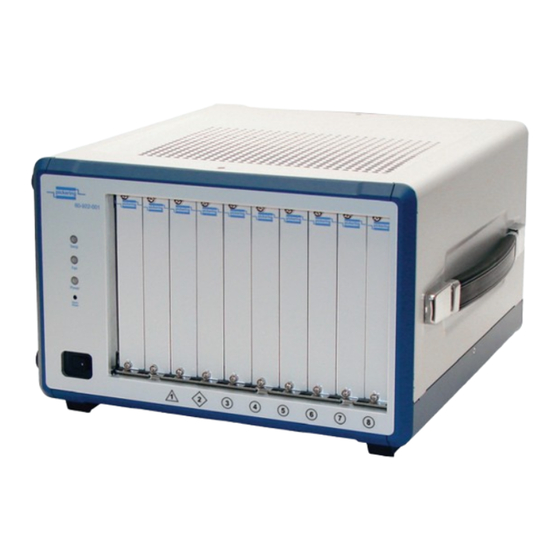
SECTION 2 - TECHNICAL DESCRIPTION pickering SECTION 2 - TECHNICAL DESCRIPTION MECHANICAL OVERVIEW The 40-922 PXI Chassis comprises the following: • Half width rack chassis also suitable for desk top operation. • 8 slot PXI/cPCI compatible backplane, Rev. 2.2 compliant. -
Page 12: Backplane Overview
SECTION 2 - TECHNICAL DESCRIPTION pickering BACKPLANE OVERVIEW Interoperability with CompactPCI The 40-922 is designed to be used with both PXI-compatible products and standard CompactPCI products. Its backplane is compliant with PXI Specification Rev. 2.2. The signals on Slot 1 of the backplane meet the requirements of the CompactPCI specification for both the peripheral and system modules. - Page 13 SECTION 2 - TECHNICAL DESCRIPTION pickering 10MHz Clock & Buffer Circuitry PXI Star Triggers LOCAL LOCAL LOCAL LOCAL LOCAL LOCAL PXI Trigger Bus Segment & PCI Bus Segment Figure 2.1 - 40-922 PXI Chassis Bus Routing 8-SLOT PXI MAINFRAME 40-922...
- Page 14 SECTION 2 - TECHNICAL DESCRIPTION pickering THIS PAGE INTENTIONALLY BLANK 8-SLOT PXI MAINFRAME 40-922 Page 2.4...
-
Page 15: Installation
The chassis can also be mounted in a 19 inch rack on a suitable equipment shelf or using Pickering’s rack mounting hardware 63-102-001. When mounted on an equipment shelf, the unit should be allocated 5U of rack space and must have its bottom feet inplace to ensure the correct flow of cooling air. - Page 16 SECTION 3 - INSTALLATION pickering Cooling Considerations The chassis draws cooling air for the PXI modules through an intake in the underside of the chassis directly below the PXI slots (see Figure 3.2). It is important not to block the passage of air into this intake.
- Page 17 SECTION 3 - INSTALLATION pickering The 40-922’s internal power supply draws cooling air through an inlet in the left hand side panel and expels air through an aperture in the rear panel (see Figures 3.4 and 3.5). During installation, It is important to ensure that these vents are not restricted and any cabling is routed away from all air inlets and outlets.
- Page 18 SECTION 3 - INSTALLATION pickering Rack Mounting The Chassis The 40-922 can be fitted into a standard 19 inch equipment rack using the optional 63-102-001 Mounting Kit. The kit consists of a frame into which the chassis is mounted that increases the overall height to 5U and allows space for cooling air to be drawn into the underside and expelled from the top of the chassis.
-
Page 19: Installation Of Individual Modules
In order to make MAX fully identify a Pickering chassis, follow these instructions: If you are obtaining the configuration ini files from the Pickering “Software Installation” disk then ignore steps 1, 2 and 6a, alternatively if you are downloading these files ignore step 6b. - Page 20 SECTION 3 - INSTALLATION pickering THIS PAGE INTENTIONALLY BLANK 8-SLOT PXI MAINFRAME 40-922 Page 3.6...
-
Page 21: Chassis Management System
SECTION 4 - CHASSIS MANAGEMENT SYSTEM pickering SECTION 4 - CHASSIS MANAGEMENT SYSTEM STATUS INDICATORS The 40-922 has a built in management system that monitors the internal chassis temperature and varies the fan speed accordingly. The system also monitors the power supply’s voltage rails and speed of the fans and indicates the chassis’... - Page 22 4. Double-click on the Setup.exe file to begin installation. Monitoring the 40-922 Using the Monitor Utility Pickering provides a GUI program (PXISRemoteMonUtil.exe) tomonitor the status of the 40-922 by a remote computer. To monitor the system using the monitor utility: 1.
- Page 23 SECTION 4 - CHASSIS MANAGEMENT SYSTEM pickering 4. Click Initialize to initialize the COM port. If the COM port is successfully initialized, the RUN button is enabled. 5. Click the RUN to display the chassis temperature, fan speed, and DC voltages. These values automatically update.
- Page 24 SECTION 4 - CHASSIS MANAGEMENT SYSTEM pickering Using the Monitoring/Control Function Library The monitoring/control function library can be used to create a customized program that can be used to remotely manage the 40-922. Refer to the data structure and function library below.
- Page 25 SECTION 4 - CHASSIS MANAGEMENT SYSTEM pickering The variables in the data structure are illustrated below: Variable Description Type Value 0: Off PowerStatus Power On/Off status BYTE 1:On Fan1Status Fan#1 operating status BYTE 0: Normal 1: Abnormal Fan2Status Fan#2 operating status...
-
Page 26: Function Reference
SECTION 4 - CHASSIS MANAGEMENT SYSTEM pickering FUNCTION REFERENCE InitCOM Description: Initializes the remote computer COM port connected to the remote monitoring port of the 40-922. Syntax: HANDLE InitCOM(LPCSTR com) Parameter: A string denotes the COM port. Can be COM1 ~ COM8. - Page 27 SECTION 4 - CHASSIS MANAGEMENT SYSTEM pickering SetChassisPowerOn Description: Powers on the 40-922. Syntax: BOOL SetChassisPowerOn (HANDLE hCom) Parameter: The initialized COM port. Return Value: TRUE if the function succeeded. FALSE if the function failed. Example: BOOL ret; ret= SetChassisPowerOn (hCom);...
- Page 28 SECTION 4 - CHASSIS MANAGEMENT SYSTEM pickering CloseCOM Description: Closes the initialized COM port. Syntax: BOOL CloseCOM(HANDLE hCom) Parameter: The initialized COM port. Return Value: TRUE if the function succeeded, FALSE if the function failed. Example: BOOL ret; ret= CloseCOM (hCom);...
-
Page 29: Maintenance
SECTION 5 - MAINTENANCE pickering SECTION 5 - MAINTENANCE Refer to the Warnings and Cautions at the front of this manual CHANGING THE FAN FILTER The air inlet in the bottom of the chassis is fitted with a filter to prevent dirt and dust from entering the chassis. The filter needs to be periodically replaced to maintain good chassis airflow. - Page 30 SECTION 5 - MAINTENANCE pickering 5. Remove the old air filter from the fan tray. 6. Peel off the protective strips on both ends of the new air filter, exposing the fixing adhesive, then stick the filter onto the fan tray edges. The new filter will need to be stretched to cover the whole fan tray length.
-
Page 31: Rack Mounting The Chassis
APPENDIX A - RACK MOUNTING pickering APPENDIX A - RACK MOUNTING THE CHASSIS To allow the 40-922 chassis to be fitted in a 19 inch equipment rack it can be simply mounted on a standard equipment shelf, or preferably, it can be fitted with the 63-102-001 rack mounting kit. The kit allows the chassis to be securely fixed in a rack with top and bottom spacing to provide the correct flow of cooling air. - Page 32 APPENDIX A - RACK MOUNTING pickering 5. Next, position the front panel against the front of the side supports so that the lip on the panel’s long edge is underneath the front edge of the base panel. 6. Secure the front panel with 6 screws as shown.
- Page 33 APPENDIX A - RACK MOUNTING pickering 10. Position the two rack handles to the left and right of the front panel and secure with 4 screws fitted from the rear of the panel as shown. 11. The finished rack mounting frame should look like the picture.
- Page 34 APPENDIX A - RACK MOUNTING pickering 14. Next, invert the frame and place it over the underside of the chassis so that the front panel fits through the aperture in the front of the frame. It will help to have the top edge of the chassis over-...
Need help?
Do you have a question about the Pxi 40-922 and is the answer not in the manual?
Questions and answers