
Related Manuals for Pickering 50-110


Summary of Contents for Pickering 50-110
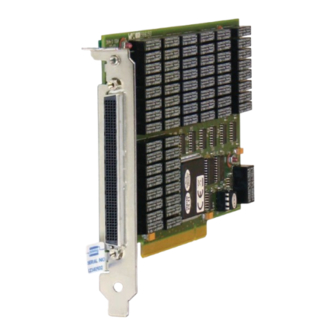
- Page 1 50-110/115/120/125 User Manual PCI Reed Relay Card pickeringtest.com Issue 7.5 May 2023...
- Page 2 Pickering Interfaces. Technical details contained within this publication are subject to change without notice. ISO 9001 Reg No. FM38792 PCI REED RELAY CARD 50-110 / 115 / 120 / 125 REED RELAY MODULE 40-110/115/120/125 Page (II) Page (II)
- Page 3 Pickering Interfaces strives to fulfil all relevant environmental laws and regulations and reduce wastes and releases to the environment. Pickering Interfaces aims to design and operate products in a way that protects the environment and the health and safety of its employees, customers and the public. Pickering Interfaces endeavours to develop and manufacture products that can be produced, distributed, used and recycled, or disposed of, in a safe and environmentally friendly manner.
-
Page 4: Product Safety
STATIC SENSITIVE To indicate that static sensitive devices are present and handling precautions should be followed. REED RELAY MODULE 40-110/115/120/125 PCI REED RELAY CARD 50-110 / 115 / 120 / 125 Page (IV) Page (IV) -
Page 5: Table Of Contents
Relay Lookup Table - 50-115-021/121 ........7.3 Relay Lookup Table - 50-115-022/122 ........7.4 Relay Lookup Table - 50-120-021 .........7.5 Relay Lookup Table - 50-125-021/121 ........7.6 Component Layout ..............7.7 PCI REED RELAY CARD 50-110 / 115 / 120 / 125 Page (V) - Page 6 THIS PAGE INTENTIONALLY BLANK PCI REED RELAY CARD 50-110 / 115 / 120 / 125 Page (VI)
-
Page 7: Warnings And Cautions
Not to be used in safety critical circuits, refer to the Pickering Interfaces’ terms & conditions of sale. This card must not be used for the switching of Mains Circuits. For the switching of voltages up to the card’s full specification, Secondary Circuit power supplies and the Device Under Test must be... - Page 8 • Ensure the equipment is installed, operated and maintained by trained and authorised personnel. • For suitably equipped products in the event of an emergency press the red “emergency stop” button situated on the front of the unit. PCI REED RELAY CARD 50-110 / 115 / 120 / 125 Page (VIII)
- Page 9 C1.2 C2.2 A25.1 A50.1 C25.1 C50.1 A25.2 A50.2 C25.2 C50.2 50-110-021 50-110-121 50-115-021 50-115-121 50-115-022 50-115-122 32xSPDT 64xSPDT 32xSPST 64xSPST 25xDPST 50xDPST Issue 9.0 April 2023 pickeringtest.com PCI REED RELAY CARD 50-110 / 115 / 120 / 125 Page 1.1...
-
Page 10: Technical Specification
Max: Mechanical Characteristics Single slot short PCI format. 3D models for all versions in a variety of popular file formats are available on request. pickeringtest.com Page 2 PCI REED RELAY CARD 50-110 / 115 / 120 / 125 Page 1.2... - Page 11 Please contact your local sales office to discuss. Pickering can supply mating 200-pin connectors and cable assemblies to enable easy integration of the 50-110 & 50-115 series of relay cards pickeringtest.com Page 3 PCI REED RELAY CARD 50-110 / 115 / 120 / 125 Page 1.3...
- Page 12 1200+ products. We offer everything from simple mating connectors to complex cables assemblies and terminal blocks. All assemblies are manufactured by Pickering and are guaranteed to mechanically and electrically mate to our modules. These accessories are detailed in Connector Accessories data sheets, where a complete list and documentation can be found for each accessory.
- Page 13 Supporting Products & Software 50-110/115 Programming Pickering provide kernel, IVI and VISA (NI & Keysight) drivers which are compatible with all Microsoft supported versions of Windows and popular older versions. For more information go to pickeringtest.com/os The VISA driver support is provided for LabVIEW Real Time Operating Systems (Pharlap and Linux-RT). For other RTOS support contact Pickering.
- Page 14 To view, download or request any of our product resources go to pickeringtest.com/resources © Copyright (2023) Pickering Interfaces. All Rights Reserved. Pickering Interfaces maintains a commitment to continuous product development, consequently we reserve the right to vary from the description given in this data sheet. pickeringtest.com Page 6 PCI REED RELAY CARD 50-110 / 115 / 120 / 125 Page 1.6...
-
Page 15: Functional Description
PCI Bridge Configuration Relays RL1-50 Relay Drivers U8-11 25xDPST or 50xDPST Card Reed Relays Configuration Figure 2.2 - Reed Relay Cards 50-115-022/122, 50-120-021 & 50-125-021/121: Functional Block Diagram PCI REED RELAY CARD 50-110 / 115 / 120 / 125 Page 2.1... - Page 16 Relays RL1-50 Relay Drivers U8-11 32xSPDT, 32xSPST or 50xSPST Card Screened Reed Relays Configuration Figure 2.3 - Screened Reed Relay Cards 50-120-021 & 50-125-021/121: Functional Block Diagram PCI REED RELAY CARD 50-110 / 115 / 120 / 125 Page 2.2...
-
Page 17: Installation
Modular products require installation in a suitable chassis. The card is designed for indoor use only. PREOPERATION CHECKS (UNPACKING) 1. Check the card for transport damage and report any damage immediately to Pickering Interfaces. Do not attempt to install the product if any damage is evident. -
Page 18: Hardware Installation
8. Power-up the host system. SOFTWARE INSTALLATION First install the appropriate Pickering PCI switch card drivers by running the installer program Setup.exe (provided in a compressed zip file), either from the CD-ROM supplied, or by downloading the latest version from our website pickeringtest.com... -
Page 19: Testing Operation
Figure 3.2 - General Soft Front Panel Icon A selector panel will appear, listing all installed Pickering PCI, PXI or LXI switch cards and resistor cards. Click on the card you wish to control, and a graphical control panel is presented allowing operation of the card. - Page 20 SECTION 3 - INSTALLATION pickering THIS PAGE INTENTIONALLY BLANK PCI REED RELAY CARD 50-110 / 115 / 120 / 125 Page 3.4...
-
Page 21: Programming Guide
SECTION 4 - PROGRAMMING GUIDE PROGRAMMING OPTIONS FOR PICKERING INTERFACES PCI CARDS For information on the installation and use of drivers and the programming of Pickering’s products in various software environments, please refer to the Software User Manual. This is available as a download from: https://www.pickeringtest.com/support/software-drivers-and-downloads... -
Page 22: Card Architecture - 50-110-021/121
CARD ARCHITECTURE - 50-110-021/121 The 50-110-021 is an array of 32, and the 50-110-121 is an array of 64 uncommitted changeover relays. In the default state, all signal paths are between the C terminal and the corresponding B terminal. Energising a particular relay disconnects the B terminal and creates a signal path between the C and A terminals. - Page 23 C58 to A58 — C59 to A59 — C60 to A60 — C61 to A61 — C62 to A62 — C63 to A63 — C64 to A64 PCI REED RELAY CARD 50-110 / 115 / 120 / 125 Page 4.3...
-
Page 24: Card Architecture - 50-115-021/121
One sub-unit is used to control all the card’s relays as shown in Table 4.2 on the following page. Enabling a particular bit closes the C to A signal path. PCI REED RELAY CARD 50-110 / 115 / 120 / 125 Page 4.4... - Page 25 C58 to A58 — C59 to A59 — C60 to A60 — C61 to A61 — C62 to A62 — C63 to A63 — C64 to A64 PCI REED RELAY CARD 50-110 / 115 / 120 / 125 Page 4.5...
-
Page 26: Card Architecture - 50-115-022/122
One sub-unit is used to control all the card’s relays as shown in Table 4.3 on the following page. Enabling a particular bit closes both C to A signal paths of the corresponding channel. PCI REED RELAY CARD 50-110 / 115 / 120 / 125 Page 4.6... - Page 27 C47.1 to A47.1 & C47.2 to A47.2 — C48.1 to A48.1 & C48.2 to A48.2 — C49.1 to A49.1 & C49.2 to A49.2 — C50.1 to A50.1 & C50.2 to A50.2 PCI REED RELAY CARD 50-110 / 115 / 120 / 125 Page 4.7...
-
Page 28: Card Architecture - 50-120-021
C24 to A24 C25 to A25 C26 to A26 C27 to A27 C28 to A28 C29 to A29 C30 to A30 C31 to A31 C32 to A32 PCI REED RELAY CARD 50-110 / 115 / 120 / 125 Page 4.8... -
Page 29: Card Architecture - 50-125-021/121
One sub-unit is used to control all the card’s relays as shown in Table 4.5 on the following page. Enabling a particular bit closes the C to A signal path. PCI REED RELAY CARD 50-110 / 115 / 120 / 125 Page 4.9... - Page 30 C44 to A44 — C45 to A45 — C46 to A46 — C47 to A47 — C48 to A48 — C49 to A49 — C50 to A50 PCI REED RELAY CARD 50-110 / 115 / 120 / 125 Page 4.10...
-
Page 31: Programming The Card
PROGRAMMING THE CARD Here are examples of using the drivers with the 50-110-121 (64 x SPDT) card. Other cards in the range operate in the same way but have a different number of bits in the sub-unit. Using PILPXI... - Page 32 SECTION 4 - PROGRAMMING GUIDE pickering THIS PAGE INTENTIONALLY BLANK PCI REED RELAY CARD 50-110 / 115 / 120 / 125 Page 4.12...
- Page 33 Figure 5.2 - Pinout: 64xSPDT Reed Relay Card 50-110-021 Relay Card 50-110-121 (200-pin Female LFH Connector (200-pin Female LFH Connector Viewed From Front of Card) Viewed From Front of Card) PCI REED RELAY CARD 50-110 / 115 / 120 / 125 Page 5.1...
- Page 34 Figure 5.4 - Pinout: 64xSPST Reed Relay Card 50-115-021 Relay Card 50-115-121 (200-pin Female LFH Connector (200-pin Female LFH Connector Viewed From Front of Card) Viewed From Front of Card) PCI REED RELAY CARD 50-110 / 115 / 120 / 125 Page 5.2...
- Page 35 Figure 5.6 - Pinout: 50xDPST Reed Relay Card 50-115-022 Relay Card 50-115-122 (200-pin Female LFH Connector (200-pin Female LFH Connector Viewed From Front of Card) Viewed From Front of Card) PCI REED RELAY CARD 50-110 / 115 / 120 / 125 Page 5.3...
- Page 36 SECTION 5 - CONNECTOR INFORMATION pickering 32 x SPDT Screened Figure 5.7 - Pinout: 32xSPDT Screened Reed Relay Card 50-120-021 (200-pin Female LFH Connector Viewed From Front of Card) PCI REED RELAY CARD 50-110 / 115 / 120 / 125 Page 5.4...
- Page 37 SA31 SC31 SA32 SC32 32 x SPDT Screened Figure 5.8 - Pinout: 32xSPST Screened Reed Relay Card 50-125-021 (200-pin Female LFH Connector Viewed From Front of Card) PCI REED RELAY CARD 50-110 / 115 / 120 / 125 Page 5.5...
- Page 38 SA47 SC47 SA48 SC48 SA49 SC49 SA50 SC50 Figure 5.9 - Pinout: 50xSPST Screened Reed Relay Card 50-125-121 (200-pin Female LFH Connector Viewed From Front of Card) PCI REED RELAY CARD 50-110 / 115 / 120 / 125 Page 5.6...
-
Page 39: Trouble Shooting
PCI configuration, highlighting any potential configuration problems. Specific details of all installed Pickering switch cards are included. All the installed Pickering switch cards should be listed in the “Pilpxi information” section - if one or more cards is missing it may be possible to determine the reason by referring to the PCI configuration dump contained in the report, but interpretation of this information is far from straightforward, and the best course is to contact Pickering support: support@pickeringtest.com, if possible... - Page 40 SECTION 6 - TROUBLE SHOOTING pickering THIS PAGE INTENTIONALLY BLANK PCI REED RELAY CARD 50-110 / 115 / 120 / 125 Page 6.2...
-
Page 41: Maintenance Information
PCB. The tables can be used in the fault finding process and should be used in conjunction with the corresponding PCB layout diagrams to identify the position of faulty relays. PCI REED RELAY CARD 50-110 / 115 / 120 / 125 Page 7.1... - Page 42 C62 to A62 C62 to B62 Not Fitted RL62 C63 to A63 C63 to B63 Not Fitted RL63 C64 to A64 C64 to B64 Not Fitted RL64 PCI REED RELAY CARD 50-110 / 115 / 120 / 125 Page 7.2...
- Page 43 Not Fitted RL60 C61 to A61 Not Fitted RL61 C62 to A62 Not Fitted RL62 C63 to A63 Not Fitted RL63 C64 to A64 Not Fitted RL64 PCI REED RELAY CARD 50-110 / 115 / 120 / 125 Page 7.3...
- Page 44 C48.1 to A48.1 & C48.2 to A48.2 Not Fitted RL48 C49.1 to A49.1 & C49.2 to A49.2 Not Fitted RL49 C50.1 to A50.1 & C50.2 to A50.2 Not Fitted RL50 PCI REED RELAY CARD 50-110 / 115 / 120 / 125 Page 7.4...
- Page 45 RL45 Not Fitted ─ ─ RL46 Not Fitted ─ ─ RL47 Not Fitted ─ ─ RL48 Not Fitted ─ ─ RL49 Not Fitted ─ ─ RL50 Not Fitted PCI REED RELAY CARD 50-110 / 115 / 120 / 125 Page 7.5...
- Page 46 Not Fitted RL46 C47 to A47 Not Fitted RL47 C48 to A48 Not Fitted RL48 C49 to A49 Not Fitted RL49 C50 to A50 Not Fitted RL50 PCI REED RELAY CARD 50-110 / 115 / 120 / 125 Page 7.6...
- Page 47 RL58 RL57 RL58 RL59 RL59 RL60 RL60 RL61 RL61 RL62 RL62 RL63 RL63 RL64 RL64 Figure 7.1 - Component Layout for 50-110-021/121 & 50-115-021/121 Relay Cards RL10 RL11 RL12 RL13 RL14 RL15 RL16 RL17 RL18 RL19 RL20 RL21 RL22 RL23...
- Page 48 SECTION 7 - MAINTENANCE INFORMATION pickering THIS PAGE INTENTIONALLY BLANK PCI REED RELAY CARD 50-110 / 115 / 120 / 125 Page 7.8...
Need help?
Do you have a question about the 50-110 and is the answer not in the manual?
Questions and answers