
Subscribe to Our Youtube Channel
Related Manuals for Pickering 40-575A


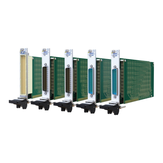
Summary of Contents for Pickering 40-575A
- Page 1 40-575A/576/577/578/579 User Manual PXI Ultra High Density 1-Pole 2 A Matrix Issue 1.2, November 2023 pickeringtest.com...
- Page 2 © Copyright (2023) Pickering Interfaces. All Rights Reserved. No part of this publication may be reproduced, transmitted, transcribed, translated or stored in any form, or by any means without the written permission of Pickering Interfaces. Technical details contained within this publication are subject to change without notice.
- Page 3 Pickering Interfaces strives to fulfil all relevant environmental laws and regulations and reduce wastes and releases to the environment. Pickering Interfaces aims to design and operate products in a way that protects the environment and the health and safety of its employees, customers and the public. Pickering Interfaces endeavours to develop and manufacture products that can be produced, distributed, used and recycled, or disposed of, in a safe and environmentally friendly manner.
-
Page 4: Product Safety
Product Safety Safety Symbols The following safety symbols may be used on the product and throughout the product documentation. Meaning/Description Symbol PROTECTIVE EARTH (GROUND) To identify any terminal which is intended for connection to an external conductor for protection against electric shock in case of a fault, or the terminal of a protective earth (ground) electrode. -
Page 5: Table Of Contents
Hardware Installation ..............................3.2 Software Installation ..............................3.2 Testing Operation ................................3.3 Section 4 Programming Guide .................................4.1 Programming Options for Pickering PXI Modules ....................4.1 Relay Cycle Counting Feature Details ........................4.1 Module Architecture ..............................4.2 Programming the Module ............................4.4 Using Pickering Drivers in LabVIEW ........................4.5 Section 5 Connector Information ..............................5.1... -
Page 6: Warnings And Cautions
Unused slots in the PXI/PXIe/LXI chassis are populated with blanking plates to prevent access to user I/O signals that may be present. Blanking panels are available to order from Pickering in a variety of slot widths. If the product is not used in this manner for example by using an extender card then additional care must be taken to avoid contact with exposed signals. - Page 7 CAUTION - Product Documentation Symbol Suitably qualified & trained users should ensure that the accompanying documentation is fully read and understood before attempting to install or operate the product. Safety Instructions Safety Instructions All cleaning and servicing requires the equipment to be isolated and disconnected from the power source and user I/O signals (refer to the Maintenance Section).
-
Page 8: Technical Specification
84x4, 1-Pole Matrix, Part Number 40-575A-001 The 40-575A-001 supports 4 concurrent switch paths for X to X and Y to X connections, however connections between different Y axis lines (e.g. Y1 to Y2, Y3 or Y4) are not permitted by the driver. - Page 9 PXI Ultra High Density Matrix 40-575A/576/577/578/579 Section 1 - Technical Specification 40-576-001 64x6 Matrix Switching Diagram The 40-576 supports 6 concurrent switch paths for X to X and Y to X connections, however connections between different Y axis lines (e.g. Y1 to any of Y2 to Y6) are not permitted by the driver.
- Page 10 The 40-579 permits 14 concurrent X to X paths or 16 concurrent Y to X paths, the 40-575A, 40-576, 40-577 and 40-578 permit 4, 6, 8 and 12 concurrent X to X or X to Y paths respectively. As an example, the 40-575A is shown in the figure below; X to Y connections (e.g.
- Page 11 † Significantly higher total switch path loading is possible PXI bus via 32-bit P1/J1 backplane connector. when using Pickering 40-922/923A PXI & 60-102B/103B LXI Signals via front panel connectors: chassis’, please contact sales office for details.
- Page 12 40-575A 93-002-001 93-002-410 Product Customization 40-576/577 93-006-001 Not Required Pickering modules are designed and manufactured on our 40-578/579 93-005-001 Not Required own flexible manufacturing lines, giving complete product Spare Relay Kits control and enabling simple customization to meet very Kits of replacement relays are available for the majority of specific requirements.
-
Page 13: Technical Description
The module comprises a mother board and a daughter board populated with 1-pole electro-mechanical relays configured as an 84x4 (40-575A), a 64x6 (40-576), a 50x8 (40-577), a 36x12 (40-578) or a 28x16 (40-579) matrix. The relays are energised via control signals from relay drivers U15-22 & U26-33. Each relay driver is loaded with serial data from PCI bridge U1 to operate the required matrix crosspoint.The main PCI interface circuitry and the drivers and relays that make up one half of... -
Page 14: Installation
Modular products require installation in a suitable PXI/LXI chassis. The module is designed for indoor use only. Pre-operation Checks (Unpacking) 1. Check the module for transport damage and report any damage immediately to Pickering Interfaces. Do not attempt to install the product if any damage is evident. -
Page 15: Hardware Installation
If you are not a LabVIEW user you should choose the “full” version, and once that has been installed run the LabVIEW Runtime Engine installer via the shortcut on the Programs>>Pickering menu. In the absence of LabVIEW the Runtime Engine is required to support the Pickering Test Panels application. -
Page 16: Testing Operation
Figure 3.2 - General Soft Front Panel Icon A selector panel will appear, listing all installed Pickering PCI, PXI/PXIe or LXI switch cards and resistor cards. Click on the card you wish to control, and a graphical control panel is presented allowing operation of the card. Panels can be opened simultaneously for all the installed cards. -
Page 17: Relay Cycle Counting Feature Details
Section 4 - Programming Programming options for Pickering Interfaces PXI Modules For information on the installation and use of drivers and the programming of Pickering’s products in various software environments, please refer to the Software User Manual. This is available as a download from: pickeringtest.com/support/software-drivers-and-downloads... - Page 18 Matrix Architecture The 40-575A is a single pole switching matrix with 84 connections on the X-axis and 4 connections on the Y-axis. Connections are made by operating the relays at the crosspoints between X and Y lines allowing single X-Y connections, or X-X connections using a Y line as a path.
- Page 19 Section 4 - Programming 40-578-001 36x12 Matrix 40-579-001 28x16 Matrix NOTE: The matrix supports concurrent switch paths for X to X and Y to X connections, however connections between different Y axis lines (e.g. Y1 to Y2) are not permitted. The entire matrix is treated as a single programming sub-unit designated as Sub-Unit 1.
- Page 20 Once the drivers are installed the manual “Sys40Prg.pdf” and driver help files which fully describes these functions can be found in the Pickering folder(s) or the Pickering entries on your Start Menu. The card must be opened before use and closed after using the following function calls: Direct Driver - Open with PIL_OpenCards or PIL_OpenSpecifiedCard and close with PIL_CloseCards or PIL_CloseSpecifiedCards respectively.
-
Page 21: Using Pickering Drivers In Labview
Section 4 - Programming Using Pickering Drivers In LabVIEW Most Pickering drivers include a LabVIEW wrapper to permit full operation of the Pickering product from the LabVIEW environment. These wrappers are normally installed to the current LabVIEW folder system during installation of the Pickering driver. - Page 22 Section 5 - Connectors Figure 5.1 - 2 A 1-Pole 84x4 Matrix Module 40-575A-001 Pinout (160-pin DIN41612 male connector pinout viewed from front of module) pickeringtest.com Page 5.1...
- Page 23 Section 5 - Connectors FP-GND Figure 5.2 - 2 A 1-Pole 64x6 Matrix Module 40-576-001: 78-pin D-type male connector pinout viewed from front of module. pickeringtest.com Page 5.2...
- Page 24 Section 5 - Connectors FP-GND Figure 5.3 - 2 A 1-Pole 50x8 Matrix Module 40-577-001: 78-pin D-type male connector pinout viewed from front of module. pickeringtest.com Page 5.3...
- Page 25 Section 5 - Connectors FP-GND Figure 5.4 - 2 A 1-Pole 36x12 Matrix Module 40-578-001: 50-pin D-type male connector pinout viewed from front of module. pickeringtest.com Page 5.4...
- Page 26 Section 5 - Connectors FP-GND Figure 5.5 - 2 A 1-Pole 28x16 Matrix Module 40-579-001: 50-pin D-type male connector pinout viewed from front of module. pickeringtest.com Page 5.5...
-
Page 27: Trouble Shooting
PCI configuration, highlighting any potential configuration problems. Specific details of all installed Pickering switch cards are included. All the installed Pickering switch cards should be listed in the “Pilpxi information” section - if one or more cards is missing it may be possible to determine the reason by referring to the PCI configuration dump contained in the report, but interpretation of this information is far from straightforward, and the support@pickeringtest.com... -
Page 28: Maintenance Information
For PXI modules which are supported in one of Pickering Interfaces’ Modular LXI Chassis (such as the 60-102D and 60-103D) no module software update is required. If the module was introduced after the LXI chassis was manufactured the module may not be recognized, in this case the chassis firmware may need upgrading. - Page 29 Mother and daughter boards share the same Y connections. Use the table below to locate which boards contain the faulty crosspoints. Also, it may help to refer to the architecture diagram in Figures 2.1 Module Number 40-575A 40-576 40-577...
- Page 30 Section 7 - Maintenance Information Relays Used in Signal Path - 40-575A (84x4 Matrix) 128 127 128 127 129 127 129 127 131 130 131 130 132 130 132 130 134 133 134 133 135 133 135 133 137 136...
- Page 31 RL87 RL126 RL125 RL124 RL82 RL83 RL84 RL100 RL101 RL102 RL123 RL122 RL121 RL97 RL98 RL99 RL115 RL116 RL117 Figure 7.2 - 40-575A Matrix Module: Motherboard Relay Locations Figure 7.3 - 40-575A Matrix Module: Daughterboard Relay Locations pickeringtest.com Page 7.4...
- Page 32 Section 7 - Maintenance Information Relays Used in Signal Path - 40-576 (64x6 Matrix) pickeringtest.com Page 7.5...
- Page 33 Section 7 - Maintenance Information RL13 RL14 RL15 RL16 RL10 RL11 RL12 RL29 RL30 RL31 RL32 RL25 RL26 RL27 RL28 RL17 RL18 RL19 RL20 RL21 RL22 RL23 RL24 RL45 RL46 RL47 RL48 RL41 RL42 RL43 RL44 RL61 RL62 RL63 RL64 RL37 RL38 RL39...
- Page 34 Section 7 - Maintenance Information Relays Used in Signal Path - 40-577 (50x8 Matrix) pickeringtest.com Page 7.7...
- Page 35 Section 7 - Maintenance Information RL10 RL11 RL12 RL13 RL14 RL15 RL21 RL22 RL23 RL24 RL25 RL26 RL27 RL28 RL29 RL30 RL31 RL32 RL33 RL34 RL35 RL41 RL42 RL43 RL44 RL45 RL51 RL46 RL47 RL48 RL49 RL50 RL61 RL62 RL63 RL64 RL65 RL52...
- Page 36 Section 7 - Maintenance Information Relays Used in Signal Path - 40-578 (36x12 Matrix) pickeringtest.com Page 7.9...
- Page 37 Section 7 - Maintenance Information RL15 RL16 RL17 RL18 RL19 RL10 RL11 RL12 RL13 RL14 RL29 RL30 RL31 RL20 RL21 RL36 RL37 RL38 RL39 RL40 RL41 RL42 RL22 RL32 RL33 RL34 RL35 RL43 RL44 RL45 RL46 RL47 RL48 RL49 RL23 RL24 RL25 RL26...
- Page 38 Section 7 - Maintenance Information Relays Used in Signal Path - 40-579 (28x16 Matrix) pickeringtest.com Page 7.11...
- Page 39 Section 7 - Maintenance Information RL19 RL27 RL26 RL25 RL24 RL23 RL22 RL21 RL20 RL37 RL38 RL39 RL10 RL18 RL17 RL16 RL15 RL14 RL13 RL12 RL11 RL40 RL41 RL42 RL43 RL44 RL45 RL46 RL54 RL53 RL52 RL51 RL50 RL49 RL48 RL47 RL28 RL29...
Need help?
Do you have a question about the 40-575A and is the answer not in the manual?
Questions and answers