
Related Manuals for Pickering PXI 40-923


Summary of Contents for Pickering PXI 40-923
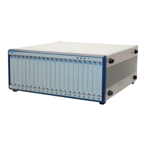
- Page 1 User Manual 19-Slot PXI Mainframe (Model No. 40-923) Issue 2.0 January 2015 pickeringtest.com pickering 19-SLOT PXI MAINFRAME 40-923 Page (1)
- Page 2 © COPYRIGHT (2015) PICKERING INTERFACES. ALL RIGHTS RESERVED. No part of this publication may be reproduced, transmitted, transcribed, translated or stored in any form, or by any means without the written permission of Pickering Interfaces. Technical details contained within this publication are subject to change without notice.
- Page 3 Pickering Interfaces strives to fulfil all relevant environmental laws and regulations and reduce wastes and releases to the environment. Pickering Interfaces aims to design and operate products in a way that protects the environment and the health and safety of its employees, customers and the public. Pickering Interfaces endeavours to develop and manufacture products that can be produced, distributed, used and recycled, or disposed of, in a safe and environmentally friendly manner.
-
Page 4: Product Safety
PRODUCT SAFETY SAFETY SYMBOLS The following safety symbols may be used on the product and throughout the product documentation. MEANING / DESCRIPTION SYMBOL PROTECTIVE EARTH (GROUND) To identify any terminal which is intended for connection to an external conductor for protection against electric shock in case of a fault, or the terminal of a protective earth (ground) electrode. -
Page 5: Table Of Contents
CONTENTS Copyright Statement ..............II Technical Support and Warranty ..........III Product Safety ................IV Contents (this page) ..............V Warnings and Cautions ..............VII Section 1 Technical Specification ...............1.1 Section 2 General Description ..............2.1 Mechanical Overview ............2.1 Backplane Overview..............2.2 Section 3 Installation ..................3.1 Installing the PXI Chassis .............3.1... - Page 6 THIS PAGE INTENTIONALLY BLANK 19-SLOT PXI MAINFRAME 40-923 Page (VI)
-
Page 7: Warnings And Cautions
Unused slots in this chassis are populated with blanking plates to prevent access to user I/O signals that may be present. Blanking panels are available to order from Pickering in a variety of slot widths. If the product is not used in this manner for example by using an extender card then additional care must be taken to avoid contact with exposed signals. - Page 8 THIS PAGE INTENTIONALLY BLANK 19-SLOT PXI MAINFRAME 40-923 Page (VIII)
-
Page 9: Technical Specification
3U peripheral modules. The control interface varies between 49.7dB and 57.7dB dependant upon can be provided by a Pickering’s 41-921 PCI to PXI the controlled fan speed which automatically responds interface kit, allowing the chassis to be controlled from to the internal chassis temperature. - Page 10 Supplied with a 700W DC output power supply with the Alternatively our web site has following capacity: dynamically linked connector/ cabling options, including pricing, for all Pickering PXI DC Output Max Current modules. +3.3V Latest Details Please refer to our Web Site for Latest Product Details.
-
Page 11: Mechanical Overview
SECTION 2 - TECHNICAL DESCRIPTION pickering SECTION 2 - TECHNICAL DESCRIPTION MECHANICAL OVERVIEW The 40-923 PXI Chassis comprises the following: • Full width rack mountable chassis also suitable for desk top operation. • 19 slot PXI/cPCI compatible backplane, Rev. 2.2 compliant. -
Page 12: Backplane Overview
SECTION 2 - TECHNICAL DESCRIPTION pickering BACKPLANE OVERVIEW Interoperability with CompactPCI The 40-923 is designed to be used with both PXI-compatible products and standard CompactPCI products. Its backplane is compliant with PXI Specification Rev. 2.2. The signals on Slot 1 of the backplane meet the requirements of the CompactPCI specification for both the peripheral and system modules. - Page 13 SECTION 2 - TECHNICAL DESCRIPTION pickering System Controller Star Trigger Controller Peripheral Slot Peripheral Slot Peripheral Slot Peripheral Slot Peripheral Slot Peripheral Slot Peripheral Slot Peripheral Slot Peripheral Slot Peripheral Slot Peripheral Slot Peripheral Slot Peripheral Slot Peripheral Slot Peripheral Slot...
- Page 14 SECTION 2 - TECHNICAL DESCRIPTION pickering THIS PAGE INTENTIONALLY BLANK 19-SLOT PXI MAINFRAME 40-923 Page 2.4...
-
Page 15: Installation
SECTION 3 - INSTALLATION pickering SECTION 3 - INSTALLATION Refer to the Warnings and Cautions at the front of this manual The chassis is designed for indoor use only. Connecting Safety Ground WARNING THE 40-923 CHASSIS IS DESIGNED WITH A THREE-POSITION IEC CONNECTOR THAT CONNECTS THE GROUND LINE TO THE CHASSIS GROUND. - Page 16 SECTION 3 - INSTALLATION pickering Cooling Considerations The chassis draws cooling air through an intake in the underside of the chassis directly below the PXI module slots (see Figure 3.2). It is important not to block the passage of air into the intake on the chassis underside. When mounting in a rack, a 1U gap should be provided between the bottom of the chassis and any other instruments to provide an unrestricted air flow into the 40-923.
-
Page 17: Selecting The 10Mhz Clock Source
SECTION 3 - INSTALLATION pickering SELECTING THE 10MHz REFERENCE CLOCK SOURCE The PXI reference clock can be used to synchronize the modules hosted by the chassis. The 40-923 can source the PXI clock from an internal high accuracy oscillator, an external clock reference (via a BNC connector on the rear panel) or from the star trigger slot. -
Page 18: Installation Of Individual Modules
In order to make MAX fully identify a Pickering chassis, follow these instructions: If you are obtaining the configuration ini files from the Pickering “Software Installation” disk then ignore steps 1, 2 and 6a, alternatively if you are downloading these files ignore step 6b. -
Page 19: Chassis Management System
SECTION 4 - CHASSIS MANAGEMENT SYSTEM pickering SECTION 4 - CHASSIS MANAGEMENT SYSTEM STATUS INDICATORS The 40-923 has a built in management system that monitors the internal chassis temperature and varies the fan speed accordingly. The system also monitors the power supply’s voltage rails and speed of the fans and indicates the chassis’... - Page 20 4. Double-click on the Setup.exe file to begin installation. Monitoring the 40-923 Using the Monitor Utility Pickering provides a GUI program (PXISRemoteMonUtil.exe) tomonitor the status of the 40-923 by a remote computer. To monitor the system using the monitor utility: 1.
- Page 21 SECTION 4 - CHASSIS MANAGEMENT SYSTEM pickering 4. Click Initialize to initialize the COM port. If the COM port is successfully initialized, the RUN button is enabled. 5. Click the RUN to display the chassis temperature, fan speed, and DC voltages. These values automatically update.
- Page 22 SECTION 4 - CHASSIS MANAGEMENT SYSTEM pickering 6. The Fan Speed Control can be set as Auto (automatically control fan speed according to internal temperature) or Maximum (force the fans to operate in full speed). 7. Click STOP to stop monitoring.
- Page 23 SECTION 4 - CHASSIS MANAGEMENT SYSTEM pickering //Temperature sensor status and reading in degree centigrade BYTE Temp1Status; BYTE Temp2Status; float Temp1Reading; float Temp2Reading; //DC status and reading BYTE DC1Status; BYTE DC2Status; BYTE DC3Status; BYTE DC4Status; float DC1Reading; float DC2Reading; float DC3Reading; float DC4Reading; BYTE Reserve1; BYTE Reserve2;...
-
Page 24: Function Reference
SECTION 4 - CHASSIS MANAGEMENT SYSTEM pickering FUNCTION REFERENCE InitCOM Description: Initializes the remote computer COM port connected to the remote monitoring port of the 40-923. Syntax: HANDLE InitCOM(LPCSTR com) Parameter: A string denotes the COM port. Can be COM1 ~ COM8. - Page 25 SECTION 4 - CHASSIS MANAGEMENT SYSTEM pickering SetChassisPowerOn Description: Powers on the 40-923. Syntax: BOOL SetChassisPowerOn (HANDLE hCom) Parameter: The initialized COM port. Return Value: TRUE if the function succeeded. FALSE if the function failed. Example: BOOL ret; ret= SetChassisPowerOn (hCom);...
- Page 26 SECTION 4 - CHASSIS MANAGEMENT SYSTEM pickering SetFanSpeedMax Description: Set fan speed control as Max mode (force the fans to operate in full speed) Syntax: BOOL SetFanSpeedMax (HANDLE hCom) Parameter: The initialized COM port Return Value: TRUE if the function succeeded, FALSE if the function failed.
-
Page 27: Maintenance
SECTION 5 - MAINTENANCE pickering SECTION 5 - MAINTENANCE Refer to the Warnings and Cautions at the front of this manual CHANGING THE FAN FILTER The air inlet in the bottom of the chassis is fitted with a filter to prevent dirt and dust from entering the chassis. The filter needs to be periodically replaced to maintain good chassis airflow. - Page 28 SECTION 5 - MAINTENANCE pickering 4. Remove the metal air inlet plate by first remove the six fixing screws. 5. Removing the metal plate allows access to the filter. 6. Replace the old filter with a new one. 7. Replace the metal plate and fasten with its six screws, then replace the two front feet, secure with their fixing screws and re-fit the rubber pads.
-
Page 29: Rack Mounting The Chassis
APPENDIX A - RACK MOUNTING pickering APPENDIX A - RACK MOUNTING THE CHASSIS To allow the 40-923 chassis to operate in a 19 inch equipment rack it can be simply mounted on a standard equipment shelf, or preferably, it can be fitted with the 63-103-001 rack mounting kit. The kit consists of side brackets that allow the chassis to be secured in a rack using fixing holes at the front and rear. - Page 30 APPENDIX A - RACK MOUNTING pickering 3. Remove the four feet on the right side of the chassis 2 by first removing their fixing screws with a cross head screwdriver. 4. Fit the two handles 3 to two of the mounting brackets 4 with the supplied M4 screws.
Need help?
Do you have a question about the PXI 40-923 and is the answer not in the manual?
Questions and answers