
Related Manuals for Pickering 41-650


Summary of Contents for Pickering 41-650
- Page 1 41-650 User Manual PXI High Voltage Amplifier Module pickeringtest.com Issue 4.3 July 2023...
- Page 2 © COPYRIGHT (2023) PICKERING INTERFACES. ALL RIGHTS RESERVED. No part of this publication may be reproduced, transmitted, transcribed, translated or stored in any form, or by any means without the written permission of Pickering Interfaces. Technical details contained within this publication are subject to change without notice.
- Page 3 Pickering Interfaces strives to fulfil all relevant environmental laws and regulations and reduce wastes and releases to the environment. Pickering Interfaces aims to design and operate products in a way that protects the environment and the health and safety of its employees, customers and the public. Pickering Interfaces endeavours to develop and manufacture products that can be produced, distributed, used and recycled, or disposed of, in a safe and environmentally friendly manner.
-
Page 4: Product Safety
If this product is heavy reference should be made to the safety instructions for provisions of lifting and moving. STATIC SENSITIVE To indicate that static sensitive devices are present and handling precautions should be followed. REED RELAY MODULE 40-110/115/120/125 HIGH VOLTAGE AMPLIFIER MODULE 41-650 Page iv Page (IV) -
Page 5: Table Of Contents
Hardware Installation ........... 3.1 Software Installation .............3.2 Soft Front Panel Installation ........3.3 Section 4 Programming Guide ............4.1 Programming Options For Pickering PXI Modules ... 4.1 Programming The Module ........... 4.2 Section 5 Connector Information ............5.1 Section 6 Trouble Shooting .............. - Page 6 THIS PAGE INTENTIONALLY BLANK HIGH VOLTAGE AMPLIFIER MODULE 41-650 Page vi...
-
Page 7: Technical Specification
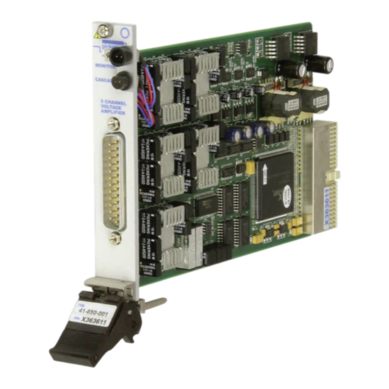
Input Output x10, x14, -S1 version) The 41-650 is a 5 channel voltage amplifier that is ideal for increasing the output voltage from other PXI modules, enabling users to easily generate the signal voltages Other commonly required in applications such as automotive test. - Page 8 High Voltage Programmable Amplifier, 41-650 17.4 0.55 0.17 41-650 High Voltage Amplifier - Typical Bandwidth Plot 41-650 High Voltage Amplifier - SINAD Plot Solid line: Input = 5.5 V peak to peak Large dashed line: Input = 0.55 V peak to peak Small dotted line: Input = 0.055 V peak to peak...
- Page 9 Signals via front panel connectors: Input Impedance: Single ended 600 Ω or 10 kΩ • 25-pin male D-type (41-650-001, 41-650-011, 41-650-001-S1) according to model • 10 x 50 Ω SMB coaxial (41-650-002, 41-650-012) Max Input Voltage: 10 V Operating/Storage Conditions Input Offset Tolerance: ±20 mV...
- Page 10 High Voltage Programmable Amplifier, 41-650 Product Order Codes Mating Connectors & Cabling Voltage Amplifier, 600 Ω, D-Type 41-650-001 For connection accessories for the 41-650 module please Voltage Amplifier, 600 Ω, SMB 41-650-002 refer to the 90-008D 25-pin D-type and...
- Page 11 We provide a full range of supporting cable and connector solutions for all our switching products—20 connector families with 1200+ products. We offer everything from simple mating connectors to complex cables assemblies and terminal blocks. All assemblies are manufactured by Pickering and are guaranteed to mechanically and electrically mate to our modules. Connectors & Backshells...
- Page 12 High Voltage Programmable Amplifier, 41-650 Programming Pickering provide kernel, IVI and VISA (NI & Keysight) drivers which are compatible with all Microsoft supported versions of Windows and popular older versions. For a list of all supporting operating systems, please see: pickeringtest.com/os...
-
Page 13: Technical Description
FUNCTIONAL DESCRIPTION The High Voltage Amplifier Module 41-650 is a high voltage multi-channel amplifier that can be used to amplify the output level of lower voltage PXI modules, such as the 41-620, to higher voltages. Each module supports up to 5 amplifier channels. -
Page 14: Cascading Monitor Ports
DMM that is likely to be part of most test systems. Some applications may require more than one 41-650 to be supported, or to allow other modules with similar monitor ports to be connected. - Page 15 The monitor port can be set to a cascade path where the input (from the DMM) is looped directly to the output (cascade) with no connection to internal parts of the 41-650, allowing modules to be connected in series. Page 2.3...
- Page 16 SECTION 2 - TECHNICAL DESCRIPTION pickering THIS PAGE INTENTIONALLY BLANK Page 2.4 HIGH VOLTAGE AMPLIFIER MODULE 41-650...
-
Page 17: Installation
Modular products require installation in a suitable PXI/LXI chassis. The module is designed for indoor use only. PREOPERATION CHECKS (UNPACKING) 1. Check the module for transport damage and report any damage immediately to Pickering Interfaces. Do not attempt to install the product if any damage is evident. -
Page 18: Hardware Installation
For a system comprising more than one chassis, turn ON the last chassis in the system followed by the penultimate, etc, and finally turn ON the external controller or chassis containing the system controller. 9. For Pickering Interfaces modular LXI installation there is no requirement to use any particular power up sequence. -
Page 19: Soft Front Panel Installation
A soft front panel is provided to allow the user to control an amplifier card. Clicking on the ‘Find Cards’ button will search attached PXI bus systems for any 41-650 series cards fitted. Any cards found will be listed in the text window and entered in the pull-down list control immediately below the ‘Find Cards’... - Page 20 SECTION 3 - INSTALLATION pickering THIS PAGE INTENTIONALLY BLANK Page 3.4 HIGH VOLTAGE AMPLIFIER MODULE 41-650...
-
Page 21: Programming Guide
SECTION 4 - PROGRAMMING GUIDE PROGRAMMING OPTIONS FOR PICKERING INTERFACES PXI MODULES For information on the installation and use of drivers and the programming of Pickering’s products in various software environments, please refer to the Software User Manual. This is available as a download from: https://www.pickeringtest.com/support/software-drivers-and-downloads... -
Page 22: Programming The Module
2.2.0, implementation 2.6.0). The pi650 driver is based on the Pickering Interfaces pipx40 driver but with the addition of specific function to control additional features of the 41-650. The programmer is advised to refer to the seperate pi650 driver manual for full details of the driver functions available. - Page 23 Gain To control the gain use the driver function : pi650_setChannelState(vi, amplifier, gain, VI_ON); For example, to set amplifier 3 to a gain of x1 :- pi650_setChannelState(vi, 3, 1, VI_ON); HIGH VOLTAGE AMPLIFIER MODULE 41-650 Page 4.3...
- Page 24 For example, to monitor channel 1 pi650_setChannelState(vi, 6, 1, VI_ON); Or, to select cascade :- pi650_setChannelState(vi, 6, 6, VI_ON); pi650_clearSub(vi, 6); HIGH VOLTAGE AMPLIFIER MODULE 41-650 Page 4.4...
- Page 25 // Read state of PSU A overload warning pi650_readInputState(vi, 1, 6, &stat); // Read offset value of channel 4 pi650_getOffsetValue(vi, 4, &data); // Set the offset of channel 5 to 255 pi650_setOffsetValue(vi, 5, 255); // close the card pi650_close(vi); HIGH VOLTAGE AMPLIFIER MODULE 41-650 Page 4.5...
- Page 26 SECTION 4 - PROGRAMMING GUIDE pickering THIS PAGE INTENTIONALLY BLANK HIGH VOLTAGE AMPLIFIER MODULE 41-650 Page 4.6...
- Page 27 SECTION 5 - CONNECTOR INFORMATION pickering SECTION 5 - CONNECTOR INFORMATION Figure 5.1 provides pin outs for the modules in the 41-650 model range. pickering pickering MONITOR MONITOR MONITOR CASCADE CASCADE CASCADE 5 CHANNEL 5 CHANNEL VOLTAGE VOLTAGE AMPLIFIER AMPLIFIER...
- Page 28 SECTION 5 - CONNECTOR INFORMATION pickering THIS PAGE INTENTIONALLY BLANK Page 5.2 HIGH VOLTAGE AMPLIFIER MODULE 41-650...
-
Page 29: Trouble Shooting
PCI configuration, highlighting any potential configuration problems. Specific details of all installed Pickering switch cards are included. All the installed Pickering switch cards should be listed in the “Pilpxi information” section - if one or more cards is missing it may be possible to determine the reason by referring to the PCI configuration dump contained in the report, but interpretation of this information is far from straightforward, and the best course is to contact Pickering support: support@pickeringtest.com, if possible... - Page 30 SECTION 6 - TROUBLE SHOOTING pickering THIS PAGE INTENTIONALLY BLANK Page 6.2 HIGH VOLTAGE AMPLIFIER MODULE 41-650...
-
Page 31: Maintenance Information
For PXI modules which are supported in one of Pickering Interfaces’ Modular LXI Chassis (such as the 60-102B and 60-103B) no module software update is required. If the module was introduced after the LXI chassis was manufactured the module may not be recognized, in this case the chassis firmware may need upgrading. -
Page 32: Instrument Checks
Load the output in 600Ω. The output level will be reduced slightly, but check the signal is still not distorted. ADJUSTMENTS The 41-650 module contains no user adjustable components. All performance numbers are achieved by use of precision components and parts that are designed to inherently meet the published specification. In the event a module fails to meet the specification a module repair must be undertaken. -
Page 33: Test Result Records
Limit Result No visible distortion on signal 3V peak, 1kHz 30V peak, open circuit Pass / Fail peaks No visible distortion on signal 3V peak, 1kHz Loaded into 600Ω Pass / Fail peaks Page 7.3 HIGH VOLTAGE AMPLIFIER MODULE 41-650... - Page 34 Limit Result No visible distortion on signal 3V peak, 1kHz 30V peak, open circuit Pass / Fail peaks No visible distortion on signal 3V peak, 1kHz Loaded into 600Ω Pass / Fail peaks Page 7.4 HIGH VOLTAGE AMPLIFIER MODULE 41-650...
- Page 35 Limit Result No visible distortion on signal 3V peak, 1kHz 30V peak, open circuit Pass / Fail peaks No visible distortion on signal 3V peak, 1kHz Loaded into 600Ω Pass / Fail peaks Page 7.5 HIGH VOLTAGE AMPLIFIER MODULE 41-650...
- Page 36 Limit Result No visible distortion on signal 3V peak, 1kHz 30V peak, open circuit Pass / Fail peaks No visible distortion on signal 3V peak, 1kHz Loaded into 600Ω Pass / Fail peaks Page 7.6 HIGH VOLTAGE AMPLIFIER MODULE 41-650...
- Page 37 Limit Result No visible distortion on signal 3V peak, 1kHz 30V peak, open circuit Pass / Fail peaks No visible distortion on signal 3V peak, 1kHz Loaded into 600Ω Pass / Fail peaks Page 7.7 HIGH VOLTAGE AMPLIFIER MODULE 41-650...
- Page 38 SECTION 7 - MAINTENANCE INFORMATION pickering THIS PAGE INTENTIONALLY BLANK Page 7.8 HIGH VOLTAGE AMPLIFIER MODULE 41-650...
Need help?
Do you have a question about the 41-650 and is the answer not in the manual?
Questions and answers