Table of Contents
Advertisement
Available languages
Available languages
Quick Links
Always connect the batteries first.
Use for 12V battery system only 12V
(36 cells) solar panel array.
Use for 24V battery system only 24V
(72 cells) solar panel array.
Use for 48V battery system only 2x24V
(72 cells) solar panel array in series.
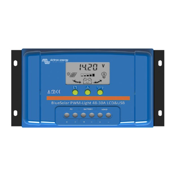
BlueSolar PWM Charge Controller – LCD - USB
12V | 24V | 30A
48V | 10A
48V | 20A
48V | 30A
www.butlertechnik.com
IMPORTANT
www.butlertechnik.com
Manual
Handleiding
Manuel
Anleitung
Manual
Manual
Manuale
Advertisement
Table of Contents

Related Manuals for Victron energy BlueSolar PWM 12V/24V 30A


Summary of Contents for Victron energy BlueSolar PWM 12V/24V 30A
- Page 1 www.butlertechnik.com Manual Handleiding Manuel Anleitung Manual IMPORTANT Manual Always connect the batteries first. Use for 12V battery system only 12V Manuale (36 cells) solar panel array. Use for 24V battery system only 24V (72 cells) solar panel array. Use for 48V battery system only 2x24V (72 cells) solar panel array in series.
- Page 2 www.butlertechnik.com www.butlertechnik.com...
-
Page 3: General Information
www.butlertechnik.com IMPORTANT Always connect the batteries first. Use for 12V battery system only 12V (36 cells) solar panel array. • Use for 24V battery system only 24V (72 cells) solar panel array. • Use for 48V battery system only 2x24V (72 cells) solar panel •... - Page 4 www.butlertechnik.com 1. Connect the battery to the charge regulator - plus and minus. 2. Connect the solar module to the regulator - plus and minus. 3. Connect the load to the charge regulator - plus and minus. The reverse order applies when deinstalling! An improper sequence order can damage the BlueSolar Charge Controller! 1.
-
Page 5: Monitoring & Settings
www.butlertechnik.com 4. LCD DISPLAY and SETTINGS MENU:switch between different display, or to enter/exit setting by long press. UP:press to change the settings when in setting mode. DOWN: press to change the settings when in setting mode. Load on/off button when in H mode. 4.1 Monitoring &... - Page 6 www.butlertechnik.com Main display. It shows battery voltage, battery capacity, charging and discharging status. Press MENU to enter next display. Battery type setting. Change Settings Main display. press on the See table below. MENU key for several seconds until The factory setting is b01 the numbers flash, you are in: Battery type...
- Page 7 www.butlertechnik.com Charge current display. It shows solar to battery current and charge status. Press MENU to enter next display. Load working mode. The factory setting is 24H Press MENU to enter next display. Load working mode setting. Change Settings in the Load working mode See table below.
-
Page 8: Short-Circuit Protection Setting
www.butlertechnik.com 10s and measure again to make sure night falls. The factory setting is 10sec Short-circuit protection Press on the MENU setting. key again and you go Some inductive or capacitive consumer will trigger the short- circuit protection during start up. -
Page 9: Over-Current Protection
www.butlertechnik.com Low battery voltage When the battery is discharged to less than the Low Voltage Disconnect (LVD) voltage, the controller will disable the load output. After over-discharge the load output will be re-enabled when the battery voltage reaches the Low Voltage Reconnect (LVR) level. -
Page 10: Specifications
www.butlertechnik.com Wiring error or short circuit in the load output circuit Wiring error: the minus of the load and the minus of the • battery are interconnected. Internal defect. • 6. Specifications BlueSolar Charge Controller 12V/24V|30A 48V|10A 48V|20A 48V|30A Battery Voltage 12/24V Auto Select Charge &... -
Page 11: Algemene Informatie
www.butlertechnik.com BELANGRIJK Altijd eerst de accu´s aansluiten. Gebruik voor 12V accusysteem een 12V (36 cellen) zonnepaneelserie. Gebruik voor 24V accusysteem een 24V (72 cellen) zonnepaneelserie. Gebruik voor 48V accusysteem een 2x24V (72 cellen) zonnepaneelserie. 1. Algemene Informatie De BlueSolar Laadregelaar serie maakt gebruik van pulsbreedtemodulatie (PWM) laadspanningsregeling gecombineerd met een meertraps laad regelalgoritme. - Page 12 www.butlertechnik.com 1. Sluit de accu aan op de laadregelaar - plus- en minteken. 2. Sluit de zonnemodus aan op de regelaar - plus- en minteken. 3. Sluit de lading aan op de laadregelaar - plus- en minteken. De omgekeerde volgorde is van toepassing bij het demonteren. Een onjuiste volgorde kan de BlueSolar Laadregelaar beschadigen! 1.
- Page 13 www.butlertechnik.com 4. LCD-SCHERM en INSTELLINGEN MENU:schakelen tussen verschillende weergaven of om de instelling te openen/sluiten door lang in te drukken. OMHOOG:indrukken om de instellingen te wijzigen in de instellingsmodus. OMLAAG: indrukken om de instellingen te wijzigen in de instellingsmodus. Laden aan-/uitknop wanneer in H-modus. www.butlertechnik.com...
- Page 14 www.butlertechnik.com 4.1 Monitoring en instellingen Waarden tussen [ ] zijn voor 24V-accu instellingen Zwart gedrukt zijn de 48V- instellingen. Opstartscherm. Na het aansluiten van de accu´s ziet u het type lader en de gemeten accuspanning. 1230 = BlueSolar Laadregelaar - LCD - USB 12V | 30A 2430 = BlueSolar Laadregelaar - LCD - USB 24V | 30A 4810 = BlueSolar Laadregelaar - LCD - USB 48V | 10A 4820 = BlueSolar Laadregelaar - LCD - USB 48V | 20A...
- Page 15 www.butlertechnik.com Laagspanning Druk op het MENU ontkoppelen toets opnieuw en u De fabrieksinstelling is bevindt zich in: 11,2V [22,4V] 44,8V Laagspanning opnieuw Druk op het MENU aansluiten toets opnieuw en u De fabrieksinstelling is bevindt zich in: 12,6V [25,2V] 50,4V Solar Spanningsdisplay.
- Page 16 www.butlertechnik.com De lading kan worden in- en uitgeschakeld door de Laad aan- /uitschakelaar. Laad D2D Het laden schakelt in bij zonsondergang en schakelt uit bij zonsopgang. L01-L23 De laaduitgang wordt na zonsondergang ingeschakeld en schakelt na 1-23 uur uit. De BlueSolar Laadregelaar levert continu stroom aan uw lading.
- Page 17 www.butlertechnik.com Laad huidige display: Het geeft de laadstroom en de accucapaciteit aan. Druk op MENU om naar het volgende scherm te gaan. USB-spanningsdisplay: Het geeft de USB-spanning aan 2A max Druk op MENU om naar het volgende scherm te gaan. Temperatuurweergave van de besturingseenheid Indien de besturingseenheid heet wordt terwijl hij is ingeschakeld, wordt deze automatisch uitgeschakeld en wacht tot de...
- Page 18 www.butlertechnik.com 5. Alarmen Wanneer de temp. ≥ 85 ℃ is, zal de regelaar naar de eerste Hoge temperatuur beveiligingsfase gaan: het PV-invoervermogen zal verlaagd worden om de temperatuur te verminderen. Er is geen alarm op het LCD-beeld. Wanneer de temp. >90 ℃ is, zal de regelaar naar de tweede beveiligingsfase gaan: het PV-invoervermogen zal verminderd worden naar nul, de laaduitgang zal uitgeschakeld worden en een alarmpictogram voor hoge temperatuur zal getoond...
- Page 19 www.butlertechnik.com Open circuit in de laadregelaar Intern defect. Open circuit in het laaduitgangcircuit Intern defect. • Bedradingsfout of kortsluiting in het laaduitgangcircuit Bedradingsfout: de minus van de laad en de minus • van de accu zijn onderling verbonden. Intern defect. •...
- Page 20 www.butlertechnik.com 6. Specificaties BlueSolar Laadregelaar 12V/24V|30A 48V|10A 48V|20A 48V|30A Accuspanning 12/24V Auto Selecteer Laden & Laadstroom Laadmodus PWM, Tijd- en Lichtregeling Automatische laadafsluiting Maximale zonnespanning 100V Zonnespanningsbereik 15-28V 30-55V 60-100V Eigen verbruik <15mA Omgekeerde polariteitsverbinding van de zonnepanelen. Omgekeerde polariteitsverbinding van de accu. Ontkoppeling met lage spanning.
-
Page 21: Consignes Générales
www.butlertechnik.com IMPORTANT Toujours connecter les batteries en premier. Pour un système de batterie de 12 V, n'utilisez que le dispositif de panneaux solaires de 12 V (36 cellules). Pour un système de batterie de 24 V, n'utilisez que le dispositif de panneaux solaires de 24 V (72 cellules). - Page 22 www.butlertechnik.com 1. Connectez la batterie au régulateur de charge – pôle positif et négatif. 2. Connectez le module solaire au régulateur – pôle positif et négatif. 3. Connectez la charge consommatrice au régulateur de charge – pôle positif et négatif. Pour désinstaller, veuillez suivre les étapes en sens inverse.
- Page 23 www.butlertechnik.com 4. ÉCRAN LCD et PARAMÈTRES MENU : pour passer d'un écran à l'autre ou pour entrer/quitter la configuration en maintenant le bouton appuyé. UP : appuyez pour modifier les paramètres lorsque vous êtes en mode Configuration. DOWN : appuyez pour modifier les paramètres lorsque vous êtes en mode Configuration.
- Page 24 www.butlertechnik.com Modifier les Configuration du type de paramètres sur batterie. l'écran principal. Voir le tableau ci-dessous. Appuyez sur le bouton MENU pendant plusieurs Le réglage standard est b01. secondes jusqu'à ce que le nombre clignote, vous arrivez dans : Type de Tension Tension Tension...
- Page 25 www.butlertechnik.com Écran de tension solaire. Il affiche la tension des panneaux solaires, le statut de la capacité de la batterie. Appuyez sur MENU pour passer à l'écran suivant. Écran de courant de charge. Il indique le courant qui va de la batterie au champ solaire et le statut du processus de charge.
- Page 26 www.butlertechnik.com valeur est élevée, plus tôt il allumera la sortie de la charge. Le réglage standard est 4/8/16 V Appuyez à nouveau Valeur du temps de retard de sur la touche MENU déclenchement L01-L23 pour vous diriger vers : (secondes) Lorsque le contrôleur de charge mesure une tension sur les panneaux solaires inférieure à...
- Page 27 www.butlertechnik.com 5. Alarmes Température élevée Lorsque la température atteint ou dépasse 85 °C, le contrôleur active la première phase de protection : il réduit le courant d’alimentation PV pour baisser la température. Aucune alarme n'apparait sur l'écran LCD. Lorsque la température atteint ou dépasse 90 °C, le contrôleur active la seconde phase de protection : il réduit et coupe le courant d’alimentation PV, il désactive la sortie de charge et affiche une icône de température élevée sur l’écran LCD.
- Page 28 www.butlertechnik.com Circuit ouvert dans le contrôleur de charge Panne interne. • Circuit ouvert dans le circuit de sortie de charge Panne interne. • Erreur de câblage ou court-circuit dans le circuit de sortie de charge Erreur de câblage : la borne (-) de la charge est •...
-
Page 29: Caractéristiques
www.butlertechnik.com 6. Caractéristiques Contrôleur de charge 12 V | 24 V | 30 A 48 V|10 A 48 V|20 A 48 V|30 A BlueSolar Sélection automatique Tension de batterie 48 V 12/24 V 10 A 20 A 30 A Charge et courant de la charge 30 A Mode de charge PWM, Contrôle de l'éclairage et du temps... - Page 30 www.butlertechnik.com www.butlertechnik.com...
-
Page 31: Allgemeine Informationen
www.butlertechnik.com WICHTIGER HINWEIS Schließen Sie immer zuerst die Batterien an. Verwenden Sie für 12 V Batterie-Systeme nur 12 V (36 Zellen) Solarmodulanlagen. Verwenden Sie für 24 V Batterie-Systeme nur 24 V (72 Zellen) Solarmodulanlagen. Verwenden Sie für 48 V Batterie-Systeme nur 2x24 V (72 Zellen) Solarmodulanlagen in Reihe. - Page 32 www.butlertechnik.com 1. Schließen Sie die Batterie an den Lade-Regler an - Plus und Minus 2. Schließen Sie das Solarmodul an den Lade-Regler an - Plus und Minus 3. Schließen Sie die Last an den Lade-Regler an - Plus und Minus Beim Deinstallieren umgekehrt vorgehen.
- Page 33 www.butlertechnik.com 4. LCD- Display und Einstellungen MENÜ:Zwischen verschiedenen Anzeigen hin- und herschalten oder Aufrufen/Verlassen der Einstellungen durch anhaltendes Drücken. HOCH: im Einstellungsmodus lassen sich damit die Einstellungen ändern. RUNTER: im Einstellungsmodus lassen sich damit die Einstellungen ändern. Taste Last ein/aus im H-Modus 4.1 Überwachung und Einstellungen Die Werte zwischen [ ] sind für 24 V-Batterieeinstellungen.
- Page 34 www.butlertechnik.com Hauptanzeigebildschirm Es wird die Batteriespannung, die Batteriekapazität, der Lade- und Entladestatus angezeigt. Durch Betätigen der Taste MENU gelangen Sie zum nächsten Bildschirm. Änderung der Einstellung des Batterietyps Einstellungen im Siehe Tabelle unten. Hauptanzeigebildschirm Halten Sie die Taste MENU Die Werkseinstellung ist b01. einige Sekunden lang gedrückt, bis die Zahlen, bei denen Sie sich gerade...
- Page 35 www.butlertechnik.com Anzeigebildschirm Ladestrom Hier wird der Solar- zu Batteriestrom und der Ladezustand angezeigt. Durch Betätigen der Taste MENU gelangen Sie zum nächsten Bildschirm. Last-Betriebs-Modus: Die Werkseinstellung ist 24 h. Durch Betätigen der Taste MENU gelangen Sie zum nächsten Bildschirm. Änderung der Last-Betriebs-Modus- Einstellungen im Last- Einstellung.
- Page 36 www.butlertechnik.com angeschlossen werden.) L01-L23 Auslösewert Bei erneutem Betätigen der Taste Verzögerung (Sekunden) Misst der Lade-Regler einen MENU gelangen Spannungswert eines Solarmoduls Sie zu folgenden unterhalb dieses Wertes, wartet er Einstellungen: 10 s lang und misst erneut, um sicherzugehen, dass die Nacht anbricht.
- Page 37 www.butlertechnik.com 5. Alarme Bei einer Temperatur ≥ 85 ℃ geht der Regler in die erste Hohe Temperatur Schutzphase über: Der PV-Eingangsstrom wird gesenkt, um die Temperatur zu reduzieren. Es erscheint kein Alarm auf dem LCD-Display. Bei einer Temperatur >90 ℃ tritt der Regler in die zweite Schutzphase ein: der PV-Eingangsstrom wird auf Null reduziert, der Lastausgang wird abgeschaltet und ein Hochtemperaturalarmsymbol wird auf der LCD-Anzeige...
- Page 38 www.butlertechnik.com Offener Stromkreis im Laderegler Interner Defekt. • Offener Stromkreis im Lastausgangskreis Interner Defekt. • Verdrahtungsfehler oder Kurzschluss im Lastausgangskreis Verdrahtungsfehler: der Minuspol der Last und der • Minuspol der Batterie sind miteinander verbunden. Interner Defekt. • www.butlertechnik.com...
-
Page 39: Technische Daten
www.butlertechnik.com 6. Technische Daten BlueSolar Lade-Regler 12 V/24 V|30 A 48 V|10 A 48 V|20 A 48 V|30 A 12/24 V automatische Batteriespannung 48 V Wahl 10 A 20 A 30 A Lade- & Last-Strom 30 A Lade-Modus PWM, Zeit- und Beleuchtungsregelung Automatische Lastabschaltung Maximale Solar-Spannung 55 V... - Page 40 www.butlertechnik.com www.butlertechnik.com...
-
Page 41: Información General
www.butlertechnik.com IMPORTANTE Conecte siempre las baterías en primer lugar. Para sistemas de batería de 12 V utilice sólo paneles solares de 12V (36 celdas). Para sistemas de batería de 24V utilice sólo paneles solares de 24V (72 celdas). Para sistemas de batería de 48V utilice sólo paneles solares de 2x24V (72 celdas). - Page 42 www.butlertechnik.com 1. Conecte la batería al controlador de carga - positivo y negativo. 2. Conecte las placas solares al controlador - positivo y negativo. 3. Conecte la carga al controlador de carga - positivo y negativo. A la hora de desinstalar, ¡siga estos pasos a la inversa! ¡Si la secuencia no se hace en este orden el controlador de carga BlueSolar podría quedar dañado! 1.
- Page 43 www.butlertechnik.com 4. PANTALLA LCD y CONFIGURACIÓN MENU:navegue entre las distintas pantallas, o introduzca/modifique ajustes manteniendo pulsado. UP (arriba):pulse para cambiar los ajustes cuando esté en modo configuración. DOWN (abajo):pulse para cambiar los ajustes cuando esté en modo configuración. Botón on/off de la carga cuando está en modo H. www.butlertechnik.com...
- Page 44 www.butlertechnik.com 4.1 Monitorización y configuración. Los valores entre [ ] corresponden a las baterías de 24V Negrita: ajustes para el modelo de 48V. Pantalla de arranque. Tras conectar la batería la pantalla muestra el tipo de cargador y la tensión del sistema detectados.
- Page 45 www.butlertechnik.com Pulse de nuevo en el Desconexión por baja tensión El ajuste de fábrica es 11,2V botón MENU [22,4V] 44,8V podrá hacer modificaciones: Reconexión por tensión baja Pulse de nuevo en el El ajuste de fábrica es 12,6V botón MENU [25,2V] 50,4V podrá...
- Page 46 www.butlertechnik.com Las cargas consumidoras puede activarse o desactivarse con el Interruptor de encendido/apagado de las cargas consumidoras. Cargas consumidoras D2D Las cargas consumidoras se activarán al anochecer y se desactivarán al amanecer. L01- La salida de cargas consumidoras se activará después del anochecer y se desactivará...
- Page 47 www.butlertechnik.com Pantalla de corriente de cargas consumidoras. Muestra la corriente de las cargas consumidoras y la capacidad de la batería. Pulse MENU para entrar en la siguiente pantalla. Pantalla de la tensión USB. Muestra la tensión USB. 2A máx. Pulse MENU para entrar en la siguiente pantalla.
- Page 48 www.butlertechnik.com 5. Alarmas Cuando la temperatura ≥ 85 ℃, el controlador entrará en la primera Temperatura alta fase de protección: la corriente de entrada FV se reducirá para bajar la temperatura. La pantalla LCD no mostrará ninguna alarma. Cuando la temperatura >90 ℃, el controlador entrará en la segunda fase de protección: la corriente de entrada FV se reducirá...
- Page 49 www.butlertechnik.com Circuito abierto en el controlador de carga Fallo interno. Circuito abierto en el circuito de salida de carga Fallo interno. Error de cableado o cortocircuito en el circuito de salida de carga Error de cableado: el negativo de la carga y el negativo •...
-
Page 50: Especificaciones
www.butlertechnik.com 6. Especificaciones Controlador de carga 12V/24V|30A 48V|10A 48V|20A 48V|30A BlueSolar Selección automática Tensión de la batería 12/24V Corriente de carga y cargas consumidoras Modo de carga PWM, Tiempo y Control de luminosidad Desconexión automática de Sí las cargas consumidoras Tensión solar máxima 100V Rango de tensión FV... -
Page 51: Allmän Information
www.butlertechnik.com VIKTIGT Anslut alltid batterierna först. Använd endast 12 V (36 cell) solcellspaneler till 12 V-batterisystem. Använd endast 24V (72 cell) solcellspaneler till 24V-batterisystem. Använd endast 2x24 V (72 cell) solcellspaneler i serie till 48 V- batterisystem. 1. Allmän information Laddningsregulatorn BlueSolar använder pulsbreddsmodulerad (PWM efter engelskans Pulse Width Modulation) laddningsspänningskontroll tillsammans med en laddingskontrollsalgoritm i flera steg. - Page 52 www.butlertechnik.com 1. Anslut batteriet - plus och minus. 2. Anslut solcellspanelen - plus och minus. 3. Anslut belastningen - plus och minus. Vid avinstallering gäller omvänd ordning. En felaktig ordning kan skada laddningsregulatorn BlueSolar! 1. Säkerställ att batteriet är laddat så att laddningsregulatorn BlueSolar kan känna igen batteritypen innan den första installationen.
- Page 53 www.butlertechnik.com 4. LCD-DISPLAY och INSTÄLLNINGAR MENY: växla mellan olika displayer eller tryck ned länge för att gå in/ur inställningar. UPP: tryck för att ändra inställningar när den är i inställningsläge. NED: tryck för att ändra inställningar när den är i inställningsläge. Belastning av/på-knapp när den är i H-läge.
- Page 54 www.butlertechnik.com 4.1 Övervakning och inställningar Värden inom [ ] är för inställningar för 24 V-batterier Fetstil är inställningarna för 48 V. Startdisplay. Efter att batteriet har anslutits visar skärmen vilken modell solcellsladdaren är samt vilken systemspänning den har. 1230= BlueSolar laddningsregulator– LCD – USB 12 V|30 A 2430= BlueSolar laddningsregulator–...
- Page 55 www.butlertechnik.com Tryck återigen ner Låg spänning frånkoppling MENY- -knappen Fabriksinställningen är och du hamnar i: 11,2 V [22,4 V] 44,8 V Låg spänning Tryck återigen ner återinkoppling MENY- -knappen Fabriksinställningen är och du hamnar i: 12,6V [25,2V] 50,4V Display för solcellsspänning. Den visar solcellsspänning och batteriets kapacitetsstatus.
- Page 56 www.butlertechnik.com Belastnignsinställning: Tryck ner MENY utlösningsvärde knappen igen och du (solcellspanelspänning) hamnar på: När driftläget är inställt på L01 (Obs: Växelriktarna L23 kommer laddningsregulatorn Phoenix VE.Direct BlueSolar att mäta spänningen i kan styras genom att solcellspanelen för att bestämma kopplas till om det är natt eller dag för att anslutningen på...
- Page 57 www.butlertechnik.com 5. Larm När temperaturen är ≥ 85 ℃, kommer regulatorn att gå in i Hög temperatur första skyddsfasen, ingångsströmmen på solcellspanelen kommer att minskas för att sänka temperaturen. LCD- displayen visar inte något larm. När temperaturen är >90 ℃, kommer regulatorn att gå in i andra skyddsfasen: ingångsströmmen på...
- Page 58 www.butlertechnik.com Öppen krets i laddningsregulatorn Invändig defekt. Öppen krets i utgångsbelastningskretsen Invändig defekt. Kabelfel eller kortslutning i utgångsbelastningskretsen Kabelfel: belastningens minus och batteriets minus • är sammankopplade. • Invändig defekt www.butlertechnik.com...
- Page 59 www.butlertechnik.com 6. Specifikationer Laddningsregulator Blue 12V/24V|30A 48V|10A 48V|20A 48V|30A Solar Batterispänning 12/24 volt autoval Laddnings- och belastningsström Laddningsläge PWM, tid- och ljuskontroll Automatisk frånkoppling av belastning Maximal solcellsspänning 100V Solpanelsintervall 15-28V 30-55V 60-100V Egenkonsumtion <15mA Omvänd polaritetsanslutning av solcellspaneler. Omvänd polaritetsanslutning av batteriet. Frånkoppling vid låg spänning.
- Page 60 www.butlertechnik.com www.butlertechnik.com...
-
Page 61: Informazioni Generali
www.butlertechnik.com IMPORTANTE Collegare sempre prima la batteria. Per sistemi di batterie da 12V utilizzare solo pannelli solari da 12V (36 celle). • Per sistemi di batterie da 24V utilizzare solo pannelli solari da 24V (72 celle). • Per sistemi di batterie da 48V utilizzare solo pannelli solari da 24V (72 celle) •... - Page 62 www.butlertechnik.com Collegare la batteria al polo positivo e negativo del regolatore di carica. Collegare il modulo solare al polo positivo e negativo del regolatore di carica. Collegare il carico al polo positivo e negativo del regolatore di carica. Per la disinstallazione si segue l’ordine inverso! Un diverso ordine della sequenza può...
- Page 63 www.butlertechnik.com 9. DISPLAY LCD e IMPOSTAZIONI MENU: passare da un display all’altro o entrare/uscire dalle impostazioni premendolo a lungo. UP: premerlo per cambiare le impostazioni quando ci si trova nella modalità di configurazione. DOWN: premerlo per cambiare le impostazioni quando ci si trova nella modalità di configurazione.
- Page 64 www.butlertechnik.com Schermata principale. Mostra la tensione batteria, lo stato di carica della batteria, lo stato di carica e di scarica. Premere MENU per entrare nella seguente schermata. Impostazioni tipo di batteria. Modifica impostazioni nella Schermata Vedere la tabella seguente. principale. Premere il pulsante MENU L'impostazione di fabbrica è...
- Page 65 www.butlertechnik.com Schermata Corrente di carica. Mostra: corrente da FV a batteria e stato di carica. Premere MENU per entrare nella seguente schermata. Modalità funzionamento carico. L'impostazione di fabbrica è 24H Premere MENU per entrare nella seguente schermata. Impostazioni Modalità Cambiare Impostazioni nella schermata funzionamento carico.
- Page 66 www.butlertechnik.com secondi ed eseguirà una nuova misurazione per assicurarsi che sia di notte. L'impostazione di fabbrica è 10 sec Impostazioni protezione Premere nuovamente il contro cortocircuito. tasto MENU e si Alcuni carichi induttivi o entra in: capacitivi attiveranno la protezione contro il cortocircuito durante l’avvio.
- Page 67 www.butlertechnik.com 5. Allarmi Quando la temperatura è ≥ 85 ℃, il regolatore entra nella Temperatura alta prima fase di protezione: la corrente di ingresso FV verrà ridotta per abbassare la temperatura. Sul display LCD non viene visualizzato alcun allarme. Quando la temperatura è >90 ℃, il regolatore entra nella seconda fase di protezione: la corrente di ingresso FV viene ridotta, l’uscita del carico verrà...
- Page 68 www.butlertechnik.com Errore di cablaggio o cortocircuito nel regolatore di carica Errore di cablaggio: il meno del pannello solare è • collegato al meno della batteria. Difetto interno. • Circuito aperto nel regolatore di carica Difetto interno. • Circuito aperto nel circuito di uscita del carico Difetto interno.
- Page 69 www.butlertechnik.com 6. Specifiche Regolatore di carica BlueSolar 12V/24V|30A 48V|10A 48V|20A 48V|30A 12/24V con selezione Tensione della batteria automatica Corrente di Carica e del Carico Modalità di carica PWM, Controllo Tempo e Illuminazione Disconnessione automatica Sì del carico Tensione fotovoltaica 100V massima Intervallo Tensione Solare 15-28V...
- Page 70 www.butlertechnik.com www.butlertechnik.com...
- Page 71 www.butlertechnik.com EN - Mechanical drawing. NL - Mechanische tekening. FR - Schémas mécaniques. DE - Technische Zeichnung ES - Dibujo mecánico. SV - Mekanisk ritning. IT - Disegni meccanici www.butlertechnik.com...
- Page 72 www.butlertechnik.com www.butlertechnik.com...
- Page 73 Serial number: Version : 05 Date : August 18 , 2020 Victron Energy B.V. De Paal 35 | 1351 JG Almere PO Box 50016 | 1305 AA Almere | The Netherlands General phone : +31 (0)36 535 97 00 E-mail : sales@victronenergy.com...
Need help?
Do you have a question about the BlueSolar PWM 12V/24V 30A and is the answer not in the manual?
Questions and answers