Table of Contents
Advertisement
Quick Links
Advertisement
Table of Contents

Related Manuals for Sears CRAFTSMAN 944-526051


Summary of Contents for Sears CRAFTSMAN 944-526051
- Page 1 DUAL STAGE Model SNOW BLOWER 944-526051 6.5 H.P. 24 inch CAUTION: You must read and understand this owner’s manual before operating unit. Serial No. ______________ 408569 08/30/06 SEARS CANADA INC., TORONTO, ONTARIO M5B 2B8 Printed in U.S.A.
-
Page 3: Hazard Symbols And The Meanings
RULES FOR SAFE OPERATION Operating Symbols and their meanings This manual contains safety information to make you These symbols are used on your equipment and defined in your operating manual. It is important that you review and understand the meanings. Failure aware of the hazards and risks associated with snow to understand the symbols might result in harm to you. - Page 4 RULES FOR SAFE OPERATION WARNING: This machine is capable ofto amputating hands and feet and throwing objects. Read these safety rules and follow them closely. Failure to obey these rules could result in loss of control of unit, severe personal injury or death to you, or bystanders, or damage to property or equipment.
- Page 5 RULES FOR SAFE OPERATION 1. Keep children out of the area and under the watchful care of another re- 2. If available, look for the relevant Emissions Durability Period and Air Index sponsible adult. information on the engine emissions label. 2.
-
Page 6: Owner's Information
LIMITED TWO (2) YEAR WARRANTY ON CRAFTSMAN SNOW BLOWER For two (2) years from date of purchase, Sears Canada Inc. will repair or replace free of charge, at Sears option, parts which are defective as a result of material or workmanship. -
Page 7: Table Of Contents
TABLE OF CONTENTS HAZARD SYMBOLS AND THE MEANINGS ..SERVICE RECOMMENDATIONS........20 ....OPERATING SYMBOLS AND THEIR MEANINGS . -
Page 8: Assembly
ASSEMBLY TOOLS REQUIRED FOR ASSEMBLY CONTENTS OF SHIPPING CARTON 1 -- Knife 1-- Snow Blower 2 -- 1/2” wrenches (or adjustable wrenches) 1-- Container of Fuel Stabilizer (Located in Parts Bag) 2 -- 9/16” wrenches (or adjustable wrenches) 1-- Snow Chute Assembly 2 -- 3/4”... -
Page 9: Unpacking
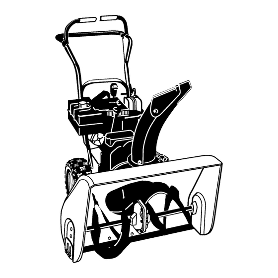
ASSEMBLY Figure 1 shows the snow blower in the shipping position. Figure 2 shows the snow blower completely assembled. Reference to right and left hand side of the snow blower is from the operator’s position at the handle. UNPACKING 1. Locate the two tear tabs at the bottom of the carton. Figure 1 Traction Drive Auger Drive... -
Page 10: Upper Handle And Crank Assembly
ASSEMBLY UPPER HANDLE AND CRANK ASSEMBLY Adaptor Boot 1. Loosen, but do not remove the screws, flatwashers, lock- Bolt washers and hex nuts in the upper holes of the lower han- Flatwasher dle. Lockwasher Nylon 2. Remove the fasteners and the crank assembly eyebolt Locknut Crank from the lower holes of the lower handle. -
Page 11: Snow Chute Assembly
ASSEMBLY SNOW CHUTE ASSEMBLY 1. Position the snow chute onto the snow chute flange. Al- ign the three holes in the snow chute with holes in snow Chute Extension chute flange. (See Figure 7) Snow Chute Deflector 2. Place three 5/16--18 carriage bolts from inside of chute as shown in Figure 7. -
Page 12: Operation
OPERATION Get to know your snow blower and its controls. Be sure you (or any other operator) have read and understood “Rules For Safe Operation” (see page 2). Gas Tank Traction Drive Choke Auger Drive Gas Cap Clutch Lever Control Clutch Lever Primer Button Traction Drive... -
Page 13: Snow Blower Operation
OPERATION The operation of any snow blower can result in foreign objects being thrown into the eyes,which can result in severe eye damage. Always wear safety glasses or eye shields before beginning snow blower Operation. We recommend standard safety glasses or Wide Vision Safety Mask for over spectacles. SNOW BLOWER OPERATION WARNING: Read Owner’s Manual before oper- ating machine. -
Page 14: Wheel Lock Out Pin
OPERATION WHEEL LOCK OUT PIN 1. The right wheel is secured to the axle with a klick pin. This unit was shipped with this klick pin in the locked position. (Figure 11). Klik Pin 2. For ease of maneuverability when lighter conditions pre- vail, remove klick pin from wheel locked position and in- sert into single wheel drive (unlocked) position (Figure 12). -
Page 15: Before Starting Engine
OPERATION BEFORE STARTING ENGINE 1. Fill the fuel tank with fresh, clean, unleaded regular, un- leaded premium, or reformulated automotive gasoline Check the oil with a minimum of 85 octane along with a fuel stabilizer (follow instructions on fuel stabilizer package). DO NOT NOTE: The engine was shipped from the factory filled use leaded gasoline. -
Page 16: Before Stopping The Engine
OPERATION BEFORE STOPPING THE ENGINE Run the engine for a few minutes to help dry off any moisture on the engine. TO STOP ENGINE CAUTION: To stop the engine, do not move the choke 2. Pull out the safety key. control to CHOKE position. - Page 17 If after following the preceding instructions, your engine fails to start, have the engine checked by an Authorized Sears Service Outlet. S Push two times if temperature is 15° F (--9° C) or high- S Push four times if temperature is below 15°...
-
Page 18: How To Cleara Clogged Discharge Chute
OPERATION FROZEN STARTER WARNING: Never run engine indoors or in en- closed, poorly ventilated areas. Engine exhaust If the starter is frozen and will not turn engine: contains CARBON MONOXIDE, AN ODORLESS 1. Pull as much rope out of the starter as possible. AND DEADLY GAS. -
Page 19: Operating Tips
OPERATION OPERATING TIPS 1. Most efficient snowblowing is accomplished when snow 6. After the snowblowing job has been completed, allow the is removed immediately after it falls. engine to idle for a few minutes, to melt snow and ice ac- cumulated on the engine. -
Page 20: Service Recommendations
SERVICE RECOMMENDATIONS SERVICE RECOMMENDATIONS FIRST BEFORE EVERY EVERY EVERY EVERY EVERY BEGINNING PROCEDURE EACH EACH BEFORE HOUR HOURS HOURS HOURS HOURS HOURS SEASON STORAGE Tighten all screws and √ √ √ nuts Check Traction Clutch Cable Adjustment √ √ (See Cable Adjustment) Check Auger clutch Cable Adjustment √... -
Page 21: Customer Responsibilities
CUSTOMER RESPONSIBILITIES Some adjustments will need to be made periodically to Remove filler plug (Figure 18), once a year. If grease is properly maintain your snow blower. visible, do not add. If grease is not visible, use a piece of fine wire, like a dipstick to check if there is grease in the gear box. -
Page 22: Lubrication -- Every 25 Hours
CUSTOMER RESPONSIBILITIES LUBRICATION - - EVERY 25 HOURS Chute Rotation Gear Chute Rotation Gear Lubricate the chute rotation gear with automotive type oil. (see Figure 19). Figure 19 Chains 4. Lubricate the chains with a chain type lubricant. 5. Wipe the hexshaft and sprockets with 5W30 motor oil. 1. -
Page 23: Engine
CUSTOMER RESPONSIBILITIES ENGINE TEMPERATURE TYPE OF OIL 0_F (- -18_ C) and above S.A.E. 5W30 POWER RATINGS 0_F (- -18_ C) and below synthetic 5W30 The power ratings for an individual engine model are initially developed by starting with SAE (Society of Automotive SAE VISCOSITY GRADES Engineers) code J1940 (Small Engine Power &... -
Page 24: Adjustment/Repair
ADJUSTMENT/REPAIR NOTE: Make sure that snow blower is set at same height WARNING: Always turn unit off, remove igni- on both sides. tion key and disconnect the spark plug wire be- fore making any repairs or adjustments. WARNING: Be certain to maintain proper ground clearance for your particular area to be AUGER HOUSING HEIGHT ADJUSTMENT cleared. -
Page 25: How To Remove The Snow Hood
ADJUSTMENT/REPAIR HOW TO REMOVE THE SNOW HOOD Mounting Screws To access the spark plug, the snow hood must be removed Snow Hood as follows: 1. Remove the choke control knob (see Figure 24). Spark Plug 2. Remove the safety key. 3. -
Page 26: Belt Adjustment
ADJUSTMENT/REPAIR BELT ADJUSTMENT Traction Drive Belt The traction drive belt has constant spring pressure and does not require an adjustment. If the traction drive belt is slipping, replace the belt. See “How To Replace The Belts” in the Maintenance section. Auger Drive Belt If your snowthrower will not discharge snow, check the control cable adjustment. -
Page 27: How To Replace The Belts
ADJUSTMENT/REPAIR HOW TO REPLACE THE BELTS The drive belts are of special construction and must be 16. Install the belt cover. Tighten screw (See Figure 28). replaced with original factory replacement belts available 17. Check the adjustment of the cables. See “How To Check from your nearest authorized service center. - Page 28 ADJUSTMENT/REPAIR Traction Drive Belt Engine Pulley Belt Guide Auger Drive Pulley Traction Drive Idler Pulley Auger Drive Belt Idler Pulley Traction Drive Spring Traction Drive Belt E--Ring Traction Drive Pulley Swing Plate Axle Rod Engine Pulley Figure 32...
- Page 29 ADJUSTMENT/REPAIR How To Remove the Traction Drive Belt If the snow thrower will not move forward, check the traction 11. Install and adjust the auger drive belt. See “How To Re- drive belt for wear or damage. If the traction drive belt is worn move The Auger Drive Belt”...
-
Page 30: Belt Guide Adjustment
ADJUSTMENT/REPAIR BELT GUIDE ADJUSTMENT 1. Remove spark plug wire. 2. Have someone engage auger drive. Belt Guide 1/8 Inch (3.175 mm) 3. Measure the distance between the belt guide and belt. The distance should be 1/8 inch (3.175 mm) for guide. Auger Idler Pulley Engaged See Figure 34. -
Page 31: Traction Drive Cable Adjustment
ADJUSTMENT/REPAIR Traction Drive Cable Adjustment Bolt WARNING: Drain the gasoline outdoors, away Bottom Panel from fire or flame. 1. Remove the gas from the gas tank. Stand the snow Auger Housing thrower up on the front end of the auger housing. 2. -
Page 32: How To Adjust Or Replace
ADJUSTMENT/REPAIR HOW TO ADJUST OR REPLACE 5. Install the bottom panel (see Figure 40). THE FRICTION WHEEL 6. Tighten the bolts on each side of the bottom panel. How To Check The Friction Wheel If the snow thrower will not move forward, check the traction Bolt Bottom Panel drive belt, the traction drive cable or the friction wheel. - Page 33 ADJUSTMENT/REPAIR How To Replace The Friction Wheel If the friction wheel is worn or damaged, the snow thrower will not move forward. The friction wheel must be replaced as follows. Drive Sprocket Axle 1. Remove the gas from the gas tank. Stand the snow thrower up on the front end of the auger housing (4).
- Page 34 ADJUSTMENT/REPAIR 10. Remove the three fasteners that hold the friction wheel to the hub (see Figure 46). 11. Remove the friction wheel from the hub. Slip the fric- tion wheel off the hex shaft. Washer 12. Assemble the new friction wheel onto hub with the fas- teners removed earlier.
-
Page 35: Auger Shear Bolt Replacement
ADJUSTMENT/REPAIR AUGER SHEAR BOLT REPLACEMENT The augers are secured to the auger shaft with special bolts NOTE: The spacer fits into the larger hole in the auger that are designed to break if an object becomes lodged in the tube. auger housing. -
Page 36: Storage
STORAGE OFF SEASON STORAGE 2. You can help keep your engine in good operating condi- WARNING: Never store engine with fuel in tank tion by changing oil before storage. indoors or in enclosed, poorly ventilated enclo- sures, where fuel fumes may reach an open 3. -
Page 37: Trouble Shooting Chart
If you have any questions concerning parts, service, or technical data, contact your nearest Sears Service Department. For complete warranty information refer to the warranty in the Owner’s Information section of this manual. - Page 38 NOTES...
-
Page 39: Repair Parts
CRAFTSMAN 24” SNOW BLOWER 944-526051 REPAIR PARTS CRAFTSMAN 24” CHASSE- NEIGE 944-526051 PIÈCES DE RECHANGE ENGINE / MOTEUR 25--2 25--1 25--3 25--4 25--2 Ref. Drive Page Ref. Auger Housing Page... - Page 40 CRAFTSMAN 24” SNOW BLOWER 944-526051 REPAIR PARTS CRAFTSMAN 24” CHASSE- NEIGE 944-526051 PIÈCES DE RECHANGE ENGINE / MOTEUR Key No. sur le Part No. schéma de pièce Description Description 198563 CORD, STARTER CORDE D MARREUR 12A113--0350--E1 ENGINE MOTEUR 198539 BOLT, CARRIAGE 5/16--18 BOULON, PO.
- Page 41 CRAFTSMAN 24” SNOW BLOWER 944-526051 REPAIR PARTS CRAFTSMAN 24” CHASSE- NEIGE 944-526051 PIÈCES DE RECHANGE GEAR CASE Key No. Part No. Description Key No. Part No. Description 73800400 NUT, HEX LOCK 1/4--20 404965 HOUSING, GEARCASE, RH 404953 WASHER, FLAT 404959 SEAL, OIL 404955 NUT,1/4--20...
- Page 42 CRAFTSMAN 24” SNOW BLOWER 944-526051 REPAIR PARTS CRAFTSMAN 24” CHASSE- NEIGE 944-526051 PIÈCES DE RECHANGE WHEELS Ref. Drive Page Key No. Part No. Description 199039X008 SHAFT, AXLE 198679 SPRKT & HUB 198667 SCREW, 1/4--20 x 1.75 73800400 NUT, 1/4--20 HEX NYLOCK 198680 BEARING, AXLE 400025...
- Page 43 CRAFTSMAN 24” SNOW BLOWER 944-526051 REPAIR PARTS CRAFTSMAN 24” CHASSE- NEIGE 944-526051 PIÈCES DE RECHANGE FRAME / BÂTI Ref. Engine Page Ref. Auger Housing Page Ref. Drive Page...
- Page 44 CRAFTSMAN 24” SNOW BLOWER 944-526051 REPAIR PARTS CRAFTSMAN 24” CHASSE- NEIGE 944-526051 PIÈCES DE RECHANGE FRAME / BÂTI Key No. sur le Part No. schéma de pièce Description Description 198573x479 COVER, BOTTOM PANNEAU INFERIEUR 198574 SCREW, 1/4--20X .63 VIS 1/4--20X .63 406663x008 IDLER ASSEMBLY, AUGER BRAS DE POULIE LIBRE.
- Page 45 CRAFTSMAN 24” SNOW BLOWER 944-526051 REPAIR PARTS CRAFTSMAN 24” CHASSE- NEIGE 944-526051 PIÈCES DE RECHANGE DRIVE / BÂTI DE MONTAGE DU MOTEUR Ref. Shift Yoke Page Ref. Frame Page Ref. Wheel Page Ref. Wheel Page Ref. Wheel Page Ref. Wheel Page...
- Page 46 CRAFTSMAN 24” SNOW BLOWER 944-526051 REPAIR PARTS CRAFTSMAN 24” CHASSE- NEIGE 944-526051 PIÈCES DE RECHANGE DRIVE / BÂTI DE MONTAGE DU MOTEUR Key No. sur le Part No. schéma de pièce Description Description 198800X008 LF AXLE, SWING PLATE YZ PANNEAU ARTICULE 579851 CHAIN, ROLLER #420 x19.00 CHAÎNE A GALETS #420 x19.00...
- Page 47 CRAFTSMAN 24” SNOW BLOWER 944-526051 REPAIR PARTS CRAFTSMAN 24” CHASSE- NEIGE 944-526051 PIÈCES DE RECHANGE AUGER HOUSING / VIS SANS FIN...
- Page 48 CRAFTSMAN 24” SNOW BLOWER 944-526051 REPAIR PARTS CRAFTSMAN 24” CHASSE- NEIGE 944-526051 PIÈCES DE RECHANGE AUGER HOUSING / VIS SANS FIN Key No. sur le Part No. schéma de pièce Description Description 45011 PULLEY, 4L 6.12X .67 POULIE 4L 6.12X .67 74950512 SCREW, 5/16--18X.63 VIS 5/16--18X.63...
- Page 49 CRAFTSMAN 24” SNOW BLOWER 944-526051 REPAIR PARTS CRAFTSMAN 24” CHASSE- NEIGE 944-526051 PIÈCES DE RECHANGE DISCHARGE CHUTE / DÉFLECTEUR DE GOULOTTE Ref. Auger Housing Page...
- Page 50 CRAFTSMAN 24” SNOW BLOWER 944-526051 REPAIR PARTS CRAFTSMAN 24” CHASSE- NEIGE 944-526051 PIÈCES DE RECHANGE DISCHARGE CHUTE / DÉFLECTEUR DE GOULOTTE Key No. sur le Part No. schéma de pièce Description Description 198648 BOLT, CARRIAGE 5/16--18 X.75 BOULON AUTOBLOQUANT 5/16--18X.75 401347 WASHER, PLASTIC RONDELLE PLASTIQUE...
- Page 51 CRAFTSMAN 24” SNOW BLOWER 944-526051 REPAIR PARTS CRAFTSMAN 24” CHASSE- NEIGE 944-526051 PIÈCES DE RECHANGE HANDLE / POIGNÊE Ref. Engine Page...
- Page 52 CRAFTSMAN 24” SNOW BLOWER 944-526051 REPAIR PARTS CRAFTSMAN 24” CHASSE- NEIGE 944-526051 PIÈCES DE RECHANGE HANDLE / POIGNÊE Key No. Part No. sur le schéma pièce Description Description 400046X479 HANDLE, UPPER POIGNEE, PARTIE SUPERIEURE 198711 SCREW, 5/16--18X2.75 VIS 5/16--18X2.75 198662 WASHER, FLAT RONDELLE PLATE 10040500...
- Page 53 CRAFTSMAN 24” SNOW BLOWER 944-526051 REPAIR PARTS CRAFTSMAN 24” CHASSE- NEIGE 944-526051 PIÈCES DE RECHANGE CHUTE ROD / GOULOTTE TIGE Ref. Handle Assy 852--9 852--5 852--13 852--8 Ref. Auger Housing Assy 852--10 852--11 852--1 852--2 852--6 852--4 852--7 852--3...
- Page 54 CRAFTSMAN 24” SNOW BLOWER 944-526051 REPAIR PARTS CRAFTSMAN 24” CHASSE- NEIGE 944-526051 PIÈCES DE RECHANGE CHUTE ROD / GOULOTTE TIGE Key No. sur le Part No. schéma de pièce Description Description 852--1 198853x008 ASSEMBLY, YOKE & ROD ENSEMBLE TRINGLE--CHAPE 852--2 198861 SPRING RESSORT...
- Page 55 CRAFTSMAN 24” SNOW BLOWER 944-526051 REPAIR PARTS CRAFTSMAN 24” CHASSE- NEIGE 944-526051 PIÈCES DE RECHANGE SHIFT YOKE / DE COMMANDE YOKE MONTAGE Key No. sur le Part No. schéma de pièce Description Description 198725x479 ROD, SHIFT TIGE DE COMMANDE DE VITESSE 198727 SCREW, 1/4--20X.75 VIS, 1/4--20X,75 PO.
- Page 56 CRAFTSMAN 24” SNOW BLOWER 944-526051 REPAIR PARTS CRAFTSMAN 24” CHASSE- NEIGE 944-526051 PIÈCES DE RECHANGE DECALS / AUTOCOLLANT SIDE OF ENGINE REF. REAR VIEW REF. REAR AUGER HOUSING Key No. sur le Part No. schéma de pièce Description Description 401364 DECAL, DANGER CHUTE HAND AUTOCOLLANT, DANGER MAINS, ÉJECTION 401366...
- Page 57 BRIGGS AND STRATTON ENGINE 12A113- 0350- E1 REPAIR PARTS MOTEUR BRIGGS AND STRATTON 12A113- 0350- E1 PIÈCES DE RECHANGE Assemblies include all parts shown in frames. Les assemblages comprennent toutes les pièces illustrées dans les encadrements.
- Page 58 BRIGGS AND STRATTON ENGINE 12A113- 0350- E1 REPAIR PARTS MOTEUR BRIGGS AND STRATTON 12A113- 0350- E1 PIÈCES DE RECHANGE Key No. sur le Part No. schéma de pièce Description Description 699510 Cylinder Assembly Cylindre 399269 Kit--Bushing/Seal (Magneto Side) Kit --entretoise/joint (face magnéto) Seal--Oil (Magneto Side) Joint à...
- Page 59 BRIGGS AND STRATTON ENGINE 12A113- 0350- E1 REPAIR PARTS MOTEUR BRIGGS AND STRATTON 12A113- 0350- E1 PIÈCES DE RECHANGE 695087 Gear--Timing Engrenage -- réglage 692564 Retainer--E Ring Bague de retenue 692566 Gear--Idler Poulie libre d’engrenage 694544 Arbre (des culbuteurs) Stud, (Rocker Arm) Seal--Valve Joint de soupape K∆692044...
- Page 60 BRIGGS AND STRATTON ENGINE 12A113- 0350- E1 REPAIR PARTS MOTEUR BRIGGS AND STRATTON 12A113- 0350- E1 PIÈCES DE RECHANGE Assemblies include all parts shown in frames. Les assemblages comprennent toutes les pièces illustrées dans les encadrements.
- Page 61 BRIGGS AND STRATTON ENGINE 12A113- 0350- E1 REPAIR PARTS MOTEUR BRIGGS AND STRATTON 12A113- 0350- E1 PIÈCES DE RECHANGE Key No. sur le Part No. schéma de pièce Description Description Gasket--Crankcase Joint de bloc--cylindre K699485 699804 Cover--Crankcase Carter de vilebrequin Seal--Oil (PTO Side) Joint à...
- Page 62 BRIGGS AND STRATTON ENGINE 12A113- 0350- E1 REPAIR PARTS MOTEUR BRIGGS AND STRATTON 12A113- 0350- E1 PIÈCES DE RECHANGE 692576 Retainer--Governor Shaft Retenue-- arbre du gouverneur 692547 Crank--Governor Manivelle du gouverneur 692653 Spring/Link--Mechanical Governor Ressort/Liaison--gouverneur Seal--Choke/Throttle Shaft Joint -- starter/ arbre d’accélérateur Dz699854 Seal--Choke/Throttle Shaft Joint -- starter/ arbre d’accélérateur...
- Page 63 BRIGGS AND STRATTON ENGINE 12A113- 0350- E1 REPAIR PARTS MOTEUR BRIGGS AND STRATTON 12A113- 0350- E1 PIÈCES DE RECHANGE Assemblies include all parts shown in frames. Les assemblages comprennent toutes les pièces illustrées dans les encadrements.
- Page 64 BRIGGS AND STRATTON ENGINE 12A113- 0350- E1 REPAIR PARTS MOTEUR BRIGGS AND STRATTON 12A113- 0350- E1 PIÈCES DE RECHANGE Key No. sur le Part No. schéma de pièce Description Description Seal--Oil (Magneto Side) Joint à huile (face magnéto) K299819 Gasket--Cylinder Head Joint de culasse K∆698210 Gasket--Crankcase...
-
Page 65: Parts Ordering Service
BRIGGS AND STRATTON ENGINE 12A113- 0350- E1 REPAIR PARTS MOTEUR BRIGGS AND STRATTON 12A113- 0350- E1 PIÈCES DE RECHANGE 1036 790550 Label--Emissions Étiquette émissions 1070 699201 Screw (Flywheel Fan) Vis (ventilateur du volant d’inertie) 1095 698215 Gasket Set--Valve Jeu de joints -- soupape 1196 696692 Screw (Snow Hood)
Need help?
Do you have a question about the CRAFTSMAN 944-526051 and is the answer not in the manual?
Questions and answers