
Related Manuals for SMC Networks VM400 Series


Summary of Contents for SMC Networks VM400 Series
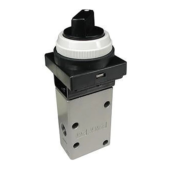
- Page 1 Document No.VM*-OMG0148-A PRODUCT NAME Mechanical valve MODEL / Series / Product Number VM400 Series...
-
Page 2: Table Of Contents
Contents 1. Safety Instructions 2~9 2. Application 3. Specifications 4. Models and Strokes 10~11 5. Installation and Mounting Orientation 6. Mechanical Operating Conditions 13~14 7. Replacement of the Actuator 15~17 8. Product Number of the Actuator... -
Page 3: Safety Instructions
Safety Instructions These safety instructions are intended to prevent hazardous situations and/or equipment damage. These instructions indicate the level of potential hazard with the labels of “Caution,” “Warning” or “Danger.” They are all important notes for safety and must be followed in addition to International Standards (ISO/IEC) , and other safety regulations. - Page 4 Safety Instructions Caution We develop, design, and manufacture our products to be used for automatic control equipment, and provide them for peaceful use in manufacturing business. Use in non-manufacturing business is not covered. Products we manufacture and sell cannot be used for the purpose of transactions or certification specified in the Measurement Act.
- Page 5 Design precautions Warning ! 1. Actuator drive When an actuator, such as a cylinder, is to be driven take appropriate measures to prevent potential danger caused by actuator operation. 2. Maintenance space When installing the products, allow access for maintenance. 3.
- Page 6 Piping Caution ! 1. Before piping Before piping, perform air blow (flushing) or cleaning to remove any cutting chips, cutting oil, dust, etc. from the piping. 2. Piping to product When piping to the product, refer to the symbols and labels on the product to avoid mistakes in the position of the supply port, etc.
- Page 7 Air Supply Warning ! 1. Use clean air. Do not use compressed air that contains chemicals, organic solvents based synthetic oils, salts or corrosive gases, etc., as this can cause damage or malfunction. Caution ! 1. Install air filters. Install air filters close to valves on the upstream side. A filtration degree of 5 micrometer or less should be selected.
- Page 8 Maintenance Warning ! 1. Removal of equipment, and supply/exhaust of compressed air When equipment is serviced, first confirm that measures are in place to prevent dropping of driven objects and/-or equipment running out of control, etc. Then cut the supply pressure and power, and exhaust all compressed air from the system using its residual pressure release function.
- Page 9 Specific Product Precautions for Mechanical Valve Design precautions Warning ! 1. Cannot be used for sealing pressure. Since the valve is subject to a little amount of air leakage, it cannot be used for applications such as holding pressure. 2. Not suitable for use as an emergency shutoff valve, etc. This valve is not designed for safety applications such as an emergency shutoff valve.
- Page 10 This could damage the mechanical valve itself and lead to equipment malfunction. Refer to Chapter 6, "Mechanical Operating Conditions" in this Operation Manual for the main precautions. Caution ! 1. After operating for a long time, it will take some time for the valve to restart as the resistance between the seal and the parts increases.
-
Page 11: Application
2. Application This product is a valve for signal transmission used for a pneumatic control circuit of machining equipment or general industrial machinery, etc. NC connection or NO connection can be selected. VM430 VM430 NC port NO port (Connection example) (Connection example)... - Page 12 F.O.F. Model Note 1 ) P.T. O.T. T.T. Actuator 0.5 MPa 3 port Note 1) Note 1) Note 1) Note 2) Basic VM430-*01-00 26 N 1.5 mm 2 mm 3.5 mm VM430-*01-01 Roller lever 12 N 4 mm 4.5 mm 8.5 mm VM430-*01-01S VM430-*01-02...
-
Page 13: Installation And Mounting Orientation
5. Installation and Mounting Orientation 5-1. Product number with each actuator Actuator Model Mounting dimensions VM430-*01-01 Roller lever VM430-*01-01S VM430-*01-02 One way roller lever VM430-*01-02S Attach it so that the lever faces upward. Fix at four points using M4 screws. Straight plunger VM430-*01-05 VM430-*01-06... -
Page 14: Mechanical Operating Conditions 13~14
6. Mechanical Operating Conditions 6-1. Stroke range Use a mechanical operating product within the stroke range calculated by the formula below. Stroke range =( P.T.+ 0.5 × O.T. )~( P.T.+ O.T.- 0.1 ) Actuator Stroke range (mm) Basic 2.5 ~ 3.4 Roller lever 6.2 ~... - Page 15 6-4. Operation mechanism and configuration 1. Avoid acute angles on limit switch actuator. Bad( × ) Good(○) Section 6-2 Not larger than the maximum angle Section 6-2 Abrupt angle Wider than the maximum angle 2. Do not allow stroke beyond the maximum travel position. Bad(...
-
Page 16: Replacement Of The Actuator 15~17
7. Replacement of the Actuator 7-1. Lever type 1. Raise the lever of the actuator as shown in Fig. and mount the actuator to the mechanical valve with two screws (M3x8). 2. Gently hit the end part of the lever support with a hammer so that the lever will not rise after mounting, and adjust the clearance between the end of the push bar and the bottom part of the lever to be not more than 1mm. - Page 17 (M3x8 with spring washer) Cross recessed round head screw (M3x8 with spring washer) Bracket Button or selector Mechanical valve [Supplied screws] Type Qty. Remarks M3x6 with spring Not required for mounting of VM400 series valve. washer M3x8 with spring washer...
- Page 18 7-4. Replacement of the button Follow the procedure below to change the button. 1. Flush push button Installation - Choose the button from 4 colors (red, green, black and yellow). Push the protruding part of the button into the body. Removal - Remove fastening ring.
-
Page 19: Product Number Of The Actuator
8. Product Number of the Actuator [Actuator number] Actuator Actuator Model Remarks Component No. Basic VM430-*01-00 ― ― VM430-*01-01 VM-01A POM roller Roller lever VM430-*01-01S VM-01AS Hard steel roller VM430-*01-02 VM-02A POM roller One way roller lever VM430-*01-02S VM-02AS Hard steel roller Straight plunger VM430-*01-05 VM-05A... - Page 20 Revision history A : Safety Instructions changed. 2023.12 4-14-1, Sotokanda, Chiyoda-ku, Tokyo 101-0021 JAPAN Tel: + 81 3 5207 8249 Fax: +81 3 5298 5362 URL https://www.smcworld.com Note: Specifications are subject to change without prior notice and any obligation on the part of the manufacturer. ©...
Need help?
Do you have a question about the VM400 Series and is the answer not in the manual?
Questions and answers