Advertisement
Quick Links
VM1000-TF222-003EN
ORIGINAL INSTRUCTIONS
Instruction Manual
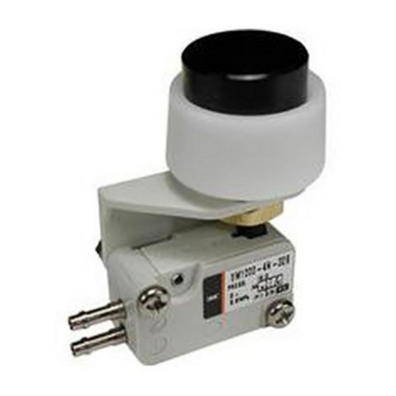
Micro Mechanical Valve
Series VM1000
The intended use of this product is to be used in pneumatic control
circuits to transmit signals at the short parts of long piping for machining
tools or general industrial machinery.
1 Safety Instructions
These safety instructions are intended to prevent hazardous situations
and/or equipment damage. These instructions indicate the level of
potential hazard with the labels of "Caution," "Warning" or "Danger."
They are all important notes for safety and must be followed in addition
*1)
to International Standards (ISO/IEC)
, and other safety regulations.
*1)
ISO 4414: Pneumatic fluid power - General rules relating to systems.
ISO 4413: Hydraulic fluid power - General rules relating to systems.
IEC 60204-1: Safety of machinery - Electrical equipment of machines.
(Part 1: General requirements)
ISO 10218-1: Robots and robotic devices - Safety requirements for
industrial robots - Part 1: Robots.
• Refer to product catalogue, Operation Manual and Handling
Precautions for SMC Products for additional information.
• Keep this manual in a safe place for future reference.
Caution indicates a hazard with a low level of risk which, if
Caution
not avoided, could result in minor or moderate injury.
Warning indicates a hazard with a medium level of risk
Warning
which, if not avoided, could result in death or serious injury.
Danger indicates a hazard with a high level of risk which, if
Danger
not avoided, will result in death or serious injury.
Warning
• Always ensure compliance with relevant safety laws and
standards.
• All work must be carried out in a safe manner by a qualified person in
compliance with applicable national regulations.
2 Specifications
2.1 Standard specifications
Valve type
N. C. poppet
Number of ports
2 or 3
Piping
Side or bottom ported
Fluid
Air
Filtration [μm]
5
Operating pressure [MPa]
0 to 0.8
Ambient and fluid temperature [ ̊ C ]
-5 to 60 (no freezing)
Flow characteristics
Refer to catalogue
Fitting
With hose nipple
Minimum operating frequency
Once every 30 days
Maximum operating frequency
1 per second
Not required (If lubricated, use
Lubrication
turbine oil Class 1 ISO VG32)
2
Note 1)
Impact resistance [
]
1000
m/s
2
Note 2)
]
Vibration resistance [
m/s
50 (0.35mm)
Mounting orientation
Unrestricted
Weight
Refer to catalogue
Total travel (T.T.) [mm]
4.8
Table 1.
Note 1) Two axes (horizontal and vertical) and two directions were tested 3 times
and no malfunction of the valve occurred (pulse shape: sine shape).
2 Specification - continued
Note 2) No malfunction occurred in a sweep cycle test between 10 to 150 Hz at
vibration sweep 0.35mm. The test was performed in the two axes and two
directions, 7 min per cycle (20 cycles).
2.2 Semi-standard specification
Total travel (T. T.) [mm]
2.5
Table 2.
Note) Only available for 'Basic' actuator type.
2.3 Definition of symbol
F.O.F.
Figure 1.
Note) Figure shows VM100 series.
• F.O.F (Full operating force): Required force to total travel position.
• P.T. (Pre-travel): From free position to initial valve operating position.
• O.T. (Over travel): From initial valve operating position to total travel
position.
• T.T. (Total travel): From free position to total travel position.
Caution
Refer to catalogue for F.O.F., P.T., O.T. and T.T. values.
2.4 ON/OFF position of the "toggle lever" option
T. T. (Total Travel) 40̊
Applicable
tubing
Note)
Figure 2.
Note) Refer to catalogue for applicable tubing.
2.5 Pneumatic symbol
Refer to catalogue for pneumatic symbol.
2.6 Special products
Warning
Special products (-X) might have specifications different from those
shown in this section. Contact SMC for specific drawings.
3 Installation
3.1 Installation
Warning
• Do not install the product unless the safety instructions have been read
and understood.
3.2 Environment
Warning
• Do not use in an environment where corrosive gases, chemicals, salt
water or steam are present.
• Do not use in an explosive atmosphere.
• Do not expose to direct sunlight. Use a suitable protective cover.
3 Installation - continued
• Do not install in a location subject to vibration or impact in excess of
the product's specifications.
• Do not mount in a location exposed to radiant heat that would result in
temperatures in excess of the product's specifications.
• Do not use in high humidity environment where condensation can
occur.
3.3 Piping
Caution
• Before connecting piping make sure to clean up chips, cutting oil, dust
etc.
• When installing piping or fittings, ensure sealant material does not
enter inside the port. When using seal tape, leave 1.5 to 2 threads
exposed on the end of the pipe/fitting.
• Tighten fittings to the specified tightening torque.
3.4 Lubrication
Caution
• SMC products have been lubricated for life at manufacture, and do not
require lubrication in service.
• If a lubricant is used in the system, refer to catalogue for details.
3.5 Air supply
Warning
• Use clean air. If the compressed air supply includes chemicals,
synthetic materials (including organic solvents), salinity, corrosive gas
etc., it can lead to damage or malfunction.
Caution
• Install an air filter upstream of the valve. Select an air filter with a
filtration size of 5 μm or smaller.
3.6 Mounting
Warning
• Do not perform mechanical operation exceeding the operation limit
position. The mechanical valve itself may be damaged leading to
equipment malfunction.
• Never perform additional machining such as enlarging the body
mounting holes as it could lead to unexpected abnormal conditions
such as air leakage.
3.6.1 Stroke range
Warning
Operate the mechanism within the stroke range given below:
Actuator
Actuator stroke [mm]
T.T. = 4.8 mm
3.7 to 4.7
Basic
T.T. = 2.5 mm
2.2 to 2.4
Roller lever
3.5 to 4.4
One way roller lever
Table 3.
3.6.2 Cam and dog angle and maximum speed
Angle limit of cam and
Max. speed limit of
Actuator type
dog
cam and dog [m/s]
Roller lever,
30°
0.7
One way roller lever
45°
0.3
Table 4.
3.7 Operation
Warning
• Operate the manual operation type mechanical valves (such as push
button, and toggle lever types) with your finger.
• The use of equipment such as a cylinder, cam or hammer, can result
in the actuator and the valve being damaged.
• Do not operate over the operation limit. If excessive operation force is
applied over total travel position, actuator part can get deformed and
lead to equipment malfunction.
• When operating the mechanical operation type mechanical valves,
select the angle and the maximum speed limit of cam and dog so that
valves do not operate over the following maximum values.
3 Installation - continued
[Acceptable]
[Not acceptable]
Over 45° (Abrupt angle)
45° or less
[Not acceptable]
[Acceptable]
Max. travel
Over travel.
Sufficient travel.
Excessive force
The actuator can
is applied due to
reach the total
the maximum
travel position
travel position
without
being exceeded
.
excessive force
being applied.
Figure 3.
Note) Figure shows VM100 series.
3.7.1 Cam and dog material
Surface finish of cam
Roller material
Cam and dog material
and dog
Polyacetal
Steel
Rz 6.3 or less
Table 5.
Caution
If the operating condition is maintained for long periods of time, it may
take some time for the valve to restart due to the adherence of the seals
and there might be a delay for recovery.
4 How to Order
Refer to catalogue for 'How to Order'.
5 Outline Dimensions
Refer to catalogue for outline dimensions.
Caution
Dimensions of the roller lever type may exceed the values specified in
the catalogue if the roller lever is positioned in any direction other than
upwards, due to the design of the lever.
6 Maintenance
6.1 General maintenance
Warning
• To prevent unexpected movements of the pneumatic actuator, the user
shall consider the state of the valve before conducting maintenance.
Additional consideration shall be given when the valve is held in the
ON position by an external mechanism such as cam, lever, etc., or in
the case that locking type valve actuators are used.
Caution
• Not following proper maintenance procedures could cause the product
to malfunction and lead to equipment damage.
• If handled improperly, compressed air can be dangerous.
• Maintenance of pneumatic systems should be performed only by
qualified personnel.
• Before performing maintenance, turn off the power supply and be sure
to cut off the supply pressure. Confirm that the air is released to
atmosphere.
• After installation and maintenance, apply operating pressure and
power to the equipment and perform appropriate functional and
leakage tests to make sure the equipment is installed correctly.
• If any electrical connections are disturbed during maintenance, ensure
they are reconnected correctly and safety checks are carried out as
required to ensure continued compliance with applicable national
regulations.
Page 1 of 2
Max. travel
Advertisement

Related Manuals for SMC Networks VM1000 Series


Summary of Contents for SMC Networks VM1000 Series
- Page 1 VM1000-TF222-003EN 2 Specification - continued 3 Installation - continued 3 Installation - continued ORIGINAL INSTRUCTIONS • Do not install in a location subject to vibration or impact in excess of [Acceptable] Note 2) No malfunction occurred in a sweep cycle test between 10 to 150 Hz at [Not acceptable] the product’s specifications.
- Page 2 VM1000-TF222-003EN 6 Maintenance - continued • Do not make any modification to the product. • Do not disassemble the product, unless required by installation or maintenance instructions. 6.2 How to change buttons on push button type - VM1000--32 Caution • To remove the button, turn it anticlockwise. •...
Need help?
Do you have a question about the VM1000 Series and is the answer not in the manual?
Questions and answers