Advertisement
Quick Links
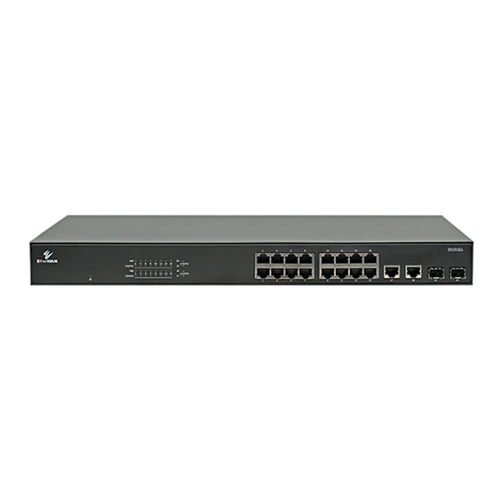
EX19162A PoE Switch Installation Guide
1
Unpacking
Unpack the items. Your package should include:
One EX19162A Ethernet PoE switch
One AC power cord
Rack-mounting hardware kit
If items are missing or damaged, notify your
EtherWAN representative. Keep the carton and
packing material.
2
What Else You Need
Category 5e or better Ethernet cables
Small form-factor pluggable (SFP) optical
transceiver modules for optional fiber
connectivity
3
Select a Location
Desktop installations: Mount on a flat table
or shelf surface.
Rack installations: Use a 19-inch EIA standard
equipment rack that is grounded and
physically secure.
Identify a power source within 6 feet (1.8
meters).
Choose a dry area with ambient temperature
between 0 and 40ºC (32 and 104ºF).
Do not cover fans on the rear and side.
Keep away from heat sources, sunlight, warm
air exhausts, hot-air vents, and heaters.
Be sure there is adequate airflow.
EX19162A
11/01/2022
Keep the switch at least 6 ft (1.83 m) away
from the nearest source of electromagnetic
noise, such as a photocopy machine.
4
Connect to the Data Ports
Sixteen Gigabit RJ45 PoE+ Ports
The switch is equipped with 16 10/100/1000
Mbps RJ45 ports that provide IEEE802.3at Power
over Ethernet (PoE+), with up to 30W per port
(250W total PoE power budget). These ports can
be connected to PoE devices such as IP
surveillance cameras or Voice Over Internet
Protocol (VoIP) phones.
A.
Insert one end of a Category 5e or better
Ethernet cable into a PoE port (ports 1 to 16)
on the switch.
B.
Connect the other end into the Ethernet port
of the device.
C.
Repeat steps A and B for each additional
device you want to connect to the switch.
Four Gigabit Data Uplink Ports
Ports 17 to 20 can be used as data uplink ports,
with ports 17 and 18 being RJ45 and ports 19 and
20 being SFP.
The SFP ports accommodate standard SFP
modules; wear an ESD-preventive wrist strap
before connecting SFP modules.
Copyright 2022 EtherWAN Systems, Inc.
All Rights Reserved
5
Apply AC Power
A.
Connect the female end of the supplied AC
power adapter cable to the power receptacle
on the switch rear panel. Connect the other
end to a grounded 3-pronged AC outlet.
B.
On the switch rear panel, move the ON/OFF
switch to the ON position.
When you apply AC power:
The fans start.
The
Power
LED goes ON.
The
Link/ACT
LEDs turn on for every port
connected to a networked device.
The
PoE
LEDs also turn on for every port
connected to a PoE powered device.
Page 1
Advertisement

Related Manuals for EtherWAN EX19162A


Summary of Contents for EtherWAN EX19162A
- Page 1 EX19162A PoE Switch Installation Guide Keep the switch at least 6 ft (1.83 m) away Unpacking Apply AC Power from the nearest source of electromagnetic Unpack the items. Your package should include: noise, such as a photocopy machine. Connect the female end of the supplied AC...
- Page 2 EX19162A PoE Switch Installation Guide Front Panel LEDs NOTES: Color Status Power Amber ON = switch is receiving power. OFF = switch is powered off. Orange ON = A Powered Device (PD) is connected (port number) to the port. OFF = No PD is connected to the port.
Need help?
Do you have a question about the EX19162A and is the answer not in the manual?
Questions and answers