Table of Contents
Advertisement
Quick Links
Instruction for use
Safety system protects human life and material assets!
Once a year functional testing by a specialist company
specialist company authorized by the manufacturer.
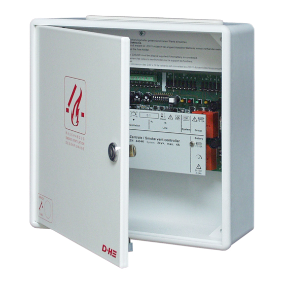
Green control diodes in the buttons must constantly lighten,
Repair power failure at once. Emergency power supply for 72 hours.
W x H x D = 250 x 250 x 91
Guarantee
You will get 2 years guarantee for all D+H products from date of verified handing over of the
system up to maximal 3 years after date of delivery, when mounting and starting has been
carried out by a D+H authorized distributor.
D+H guarantee is expired, with connection of D+H components with external systems or
with mixing of D+H products with parts of other manufacturers.
D+H Mechatronic AG • Georg-Sasse-Str. 28-32 • D-22949 Ammersbek • Tel. +4940-60565219 • Fax +4940-60565264
Smoke Vent System RZN 4402/04-K
authorized by the manufacturer.
Connection, mounting and functional testing by a
otherwise see "Informations for Starting".
RZN 4402-K
RZN 4404-K
installation
Approval-
Number:
G 501002
RZN 4402-KS
RZN 4404-KS
W x H x D = 400 x 300 x 120
Advertisement
Table of Contents

Related Manuals for D+H RZN 4404-K


Summarization of Contents
Technical Data and Maintenance
Technical Data
Provides detailed specifications for control panel type, voltage, capacity, emission, and protection.
Maintenance Procedures
Details annual maintenance by authorized specialists, including inspection, resistance checks, and functional testing.
Maintenance Information
Explains system indicators for overdue maintenance and malfunction, and consequences of expired maintenance time.
Introduction to Smoke and Heat Vent Systems
Importance of Professional Maintenance
Highlights that only authorized specialist companies ensure permanent functional safety and system reliability.
Housing Mounting - Part 2
Accumulator Fastening
Instructions for fastening accumulators, specifically for the RZN 4404-K model.
Drives and Smoke Vent Openings
Drive Mounting Instructions
Refers to specific drive instructions and provides ATTENTION notes regarding dip switch 10 and VdS 2581 compliance.
Wiring Plan Overview
230V Power Supply Connection
Instructions for connecting the 230V mains supply, including fuse requirements and cable specifications.
Weak Current Line Installation
Guidance on installing and feeding weak current lines separately from supply mains, including cable marking.
Cable Specifications and Requirements
Control Cable (Group) Details
Specifies functional conservation requirements (E30/MLAR) for control cables connecting the panel to drives.
Detector Cable Specifications
Covers monitoring for short circuits/breaks, trigger conditions, and cable types (YR, IY(ST)Y) for detector lines.
Line Lengths and Cross-Sections
Provides a table detailing maximum line lengths and required cross-sections for different drive configurations.
Standard Connection Diagrams - RT 42
Terminal Resistors for Line Monitoring
Explains the purpose and placement of terminal resistors for line monitoring of detectors and external controls.
Approved Fire Detectors
Specifies that only D+H system approved detectors must be used.
Standard Connection Diagrams - RT 43-H/-N
Terminal Resistors for Line Monitoring (RT 43)
Explains the purpose and placement of terminal resistors for line monitoring with RT 43-H/-N buttons.
Approved Fire Detectors (RT 43 Context)
Reiterates the requirement to use only D+H system approved detectors.
Connecting Multiple Fire Detectors
Magnetic Clamp Connection
Shows how to connect magnetic clamps to the RZN 4400-K, with a warning about low tension side.
Connection Examples and Line Derivation
Connection Example: Single Line
Simple installation with all drives on one line, noting potential voltage drop issues.
Connection Example: Two Lines
Control panel in center, one side derivation, other terminal line. Requires 4 wires for derivation.
Connection Example: Two Lines (One Side)
Derivation and terminal lines in the same direction. Number of drives varies by line length.
Connection Example: Three Lines
Configuration for extremely long distances with 3 lines and multiple drives distributed across them.
Periodic Examination and Testing
Examination Preparation Steps
Instructions for notifying users, handling false alarms, and disabling monitoring before starting an inspection.
Examination Information and Indicators
Explains system indicators for overdue maintenance and malfunctions, and the impact of maintenance expiry.
Inspection Procedures
Details checks for physical damage, dirt, and functional impairment of components and system parts.
Smoke Vent Button Functional Test
Step-by-step guide to test the smoke vent button's open/close function and indicator lights.
Automatic Fire Detector Testing
Procedures for testing automatic fire detectors using a tester or cigarette smoke, and resetting the line.
External Control Function Test
How to test the external control input for opening and closing the smoke vent.
Emergency Supply Test
Instructions for testing the emergency supply by detaching the mains fuse and checking indicator lights.
Need help?
Do you have a question about the RZN 4404-K and is the answer not in the manual?
Questions and answers