Sign In
Upload
Manuals
Brands
Nidec Manuals
Controller
MCE Motion 2000 Touch Screen
Nidec MCE Motion 2000 Touch Screen Manuals
Manuals and User Guides for Nidec MCE Motion 2000 Touch Screen. We have
1
Nidec MCE Motion 2000 Touch Screen manual available for free PDF download: User Manual
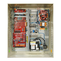
Nidec MCE Motion 2000 Touch Screen User Manual (244 pages)
Hydraulic Controller
Brand:
Nidec
| Category:
Controller
| Size: 31 MB
Table of Contents
Safety Precautions
4
Environmental Considerations
5
Air Conditioned Equipment Cabinets
5
In this Manual
6
Table of Contents
7
Section 1. M2000 TS Description
13
General Information
13
Car Controller Description
15
Controller Circuit Boards
17
MC-CPI-2 Car Panel Interface Board
21
Specifications
22
Operating Mode Descriptions
24
Non-Automatic Modes
24
Inspection Operation
25
Cartop Inspection
25
In Car Inspection
25
Hoistway Access Inspection
26
Machine Room Inspection
26
Construction Operation
27
Automatic Modes of Operation
27
Test Mode
27
Fire Service Operation
27
Emergency Medical Service Mode
28
CFSS Recall Mode
28
CFSS Phase II (In-Car) Mode
29
Recall Switch Mode
29
Independent Service Mode
29
Attendant Mode
30
Sabbath Mode
30
Capture for Test (Pretest) Mode
31
Passenger (Automatic) Mode of Operation
31
Operational States
31
Earthquake Operational State
32
Emergency Power Operational State
32
Emergency Dispatch Operational State
32
Pit Flood Operational State
32
User Interface
33
Home Screen
33
Mode of Operation
33
Faults and Safety
34
System Status
34
Menu Overview
36
Landing System
39
LS-EDGE Landing System
39
Section 2. Installation
41
In this Section
41
Safety Precautions
42
Personal Safety
42
Equipment Safety
42
Installation Considerations
43
Machine Room Preparation
43
Piping and Wiring
44
How Electrical Noise Occurs
44
How to Avoid Electrical Noise Problems
44
Possible EMI/RFI Interference
44
Recommended Tools and Test Equipment
45
Wiring Prints
45
Drawing Number Format
45
Nomenclature
46
Controller Installation
47
Controller Wiring Guidelines
47
General Wiring Guidelines
48
Proper Grounding Procedures
48
Wiring Connections for Properly Grounded Systems
48
Ground Wiring
48
Main AC Power
49
Pump Motor Wiring
49
Low Voltage Signal Wiring
49
Traveling Cable Wiring
49
In this Section
51
Check for Shorts to Ground
52
Before Applying Power
52
Applying Power
53
Initial Adjustments and Power Phasing
53
Set up for Construction Operation
54
Settings and Jumpers
54
Temporary Jumpers
55
Temporary Run Box Hookup
56
Verifying Proper Starter Operation
57
Hoistway Control Equipment Installation
59
LS-EDGE Installation
59
LS-EDGE Tape Installation
60
LS-EDGE Top Hanger Assembly
60
LS-EDGE Bottom Hanger Assembly
61
LS-EDGE Broken Tape Switch
62
Hanging the Tape
62
LS-EDGE Sensor Installation
62
LS-EDGE Door Zone Magnets
64
LS-EDGE Terminal Magnets
65
LS-EDGE Terminal Magnet Logic
67
LS-EDGE Electrical Connection
67
Parameter Settings
67
Hoistway Learn Operation
68
Hoistway Learn (Landing System Learn)
68
Construction Learn
68
Motion 2000 TS Hydro Adjustment
68
Adjusting Floor Heights
68
Door Position Monitor Switch (if Used)
69
LS-EDGE Short Floors
70
Door Zone Verification
70
Permanently Attach Magnets
70
Complete the Installation and Field Wiring
71
Preparing the Car to Run on Test/Normal Mode
71
In this Section
73
Diagnostic Messages and Input/Output Signals
74
Troubleshooting Reference
75
System I/O
75
System Diagnostics
75
CAR, MOTION, GROUP, PLD Diagnostics
76
Action Info
76
Status Info
76
Stats
77
Scope
77
Test Mode Operation
78
Running on Test/Normal Mode
79
Final Adjustments on Test Mode
80
Hydraulic Valves
80
Slowdown and Limit Switches
80
Motor/Valve Limit Timer
80
Relevel Operation
80
Final Adjustments on Independent Service
81
Door Operator Adjustments
81
Door Open/Close Protection
81
Final Adjustments on Normal Operation
82
Hall Calls
82
Ride and Performance
82
Recheck
82
Options
82
Remote Governor Testing (Roped Hydro)
83
Static Testing
83
Dynamic Testing
83
Final Testing, LS-EDGE Only
84
Bottom Terminal Slowdown Limit Tests
84
Top Terminal Slowdown Limit Tests
84
Stop Ring Test
85
Low Oil Condition Testing
86
Low Oil Switch in Use
86
No Low Oil Switch in Use
86
Passcode (Restricted Mode)
87
Release to Normal Operation
88
Section 5. the Computer
89
In this Section
89
The HC-MPU-2-TS Main Processor Unit
90
Indicators
90
Buttons and Adjustment Connectors
91
Using the Touch Screen
92
Home
92
Shortcuts
94
Screen Descriptions
95
Spare Input and Spare Output Tables
113
Troubleshooting Reference
125
Bus Voltage Testpoints and Fuse Locations
125
Touch Screen Tools
126
System I/O
126
System Diagnostics
126
CAR, MOTION, GROUP, PLD Diagnostics
127
Action Info
127
Status Info
127
Stats
128
Scope
128
Circuit Board Descriptions
128
MC-LSI Landing System Interface Board
129
LSI Connections
129
SC-3HN Three Input Serial Hall Call Node Board
231
Call Bus Conditions
231
General Installation
231
Addressing and CAN Bus Termination
233
Riser Assignment
233
Floor Number and Front or Rear Opening
233
Baud Rate
233
CAN Bus Termination
233
On Board Diagnostics
234
On Led
234
(Flt) Fault Led
234
Inventory
234
Advertisement
Advertisement
Related Products
Nidec MCE Motion 2000 TS
Nidec SI-Interbus 2 MBd
Nidec 22765-01
Nidec RINGCONE 200B
Nidec RINGCONE 2200
Nidec SI-I/O 24 Plus
Nidec D2-018
Nidec D2-034
Nidec D2-042
Nidec D2-048
Nidec Categories
Measuring Instruments
DC Drives
Industrial Equipment
Controller
Test Equipment
More Nidec Manuals
Login
Sign In
OR
Sign in with Facebook
Sign in with Google
Upload manual
Upload from disk
Upload from URL