Advertisement
Quick Links
Advertisement

Related Manuals for Baxton Studio Studio Elsbeth Japandi BSLC22040703


Summary of Contents for Baxton Studio Studio Elsbeth Japandi BSLC22040703
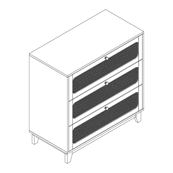
- Page 1 Chest of drawers ASSEMBLY INSTRUCTION Date last updated:07-27-2022...
-
Page 2: Hardware List
HARDWARE LIST 31 PCS 31 PCS 22 PCS 24 PCS 42 PCS 3 PCS 4 PCS 8 PCS Ø3.5x12mm 1 PCS 4 PCS 2 PCS 2 PCS 19 PCS 8 PCS 3 PCS 3 PCS 3 PCS 3 PCS... -
Page 3: Parts List
PARTS LIST 1- 1PCS 2- 1PCS 3- 1PCS 4- 1PCS 5- 1PCS 6- 1PCS 7- 1PCS 8- 2PCS 9- 2PCS 10- 2PCS 11- 2PCS 12- 2PCS 13- 3PCS 14- 3PCS 15- 3PCS 16- 3PCS 17- 3PCS 18- 3PCS... -
Page 4: Assembly Steps
ASSEMBLY STEPS STEP 1. Fix outer drawer runners (CL) and (CR) to part 2 and part 3 using screws (E), as shown. E x24 CR x3 CL x3 STEP 2. Insert quickfit screws (A) into parts 2 and 3, as shown. A x8... - Page 5 ASSEMBLY STEPS STEP 3. Insert cam locks (B) and wooden dowels (C) into parts 5, 6 and 7, as shown. Attach parts 5, 6 and 7 to part 2. Turn cam locks clockwise to tighten. B x4 C x2 STEP 4. Insert cam locks (B) and wooden dowels (C) into parts 5, 6 and 7, as shown.
- Page 6 ASSEMBLY STEPS STEP 5. Slide part 8 into grooves between parts 2, 5 and 3, as shown. STEP 6. Insert quickfit screws (A) into part 1, as shown. A x4...
- Page 7 ASSEMBLY STEPS Insert cam locks (B) and wooden dowels (C) into parts 2 and 3, as shown. STEP 7. Fit part 1 to parts 2 and 3, as shown. Turn cam locks clockwise to tighten. Secure part 1 to part 6 using screws (D), as shown. B x4 C x6 D x2...
- Page 8 ASSEMBLY STEPS STEP 9. Fix part 4 to assembled unit with wooden dowels (C) and screws (D), as shown. C x4 D x4 STEP 10. Insert quickfit screws (A) into parts 9 and 11, as shown. A x4...
- Page 9 ASSEMBLY STEPS STEP 11. G x4 I x1 Insert nuts (G-2) into parts 12, as shown. Fix parts 9 and 11 to parts 12 using bolts (G-1) and allen key (I), as shown. STEP 12. Insert cam locks (B) into parts 10. Fit parst 10 to parts 9 and 11, as shown.
- Page 10 ASSEMBLY STEPS STEP 13. C x8 H x8 Insert wooden dowels (C) into part 4. Fix assembled legs to part 4 using screws (H), as shown. STEP 14. Fix foot nails (J) to legs 9 and 11, as shown. Attach screw covers (M) to the legs, as shown. J x4 M x4...
- Page 11 ASSEMBLY STEPS Insert quickfit screws (A) into parts 13, STEP 15. as shown. Fix handles (F-2) to parts 13 using screws (F-1), as shown. A x15 B x15 Fix parts 14, 16 and 18 to parts 15 using screws (D), as shown. D x18 F x3 M x15...
- Page 12 ASSEMBLY STEPS STEP 16. E x18 DL x3 DR x3 Fix inner drawer runners (DL) and (DR) to assembled drawers using screws (E), as shown. STEP 17. Fit drawers into assembled unit, as shown.
- Page 13 ASSEMBLY STEPS STEP 18. Fix wall starps (K-1) on to parts 2 and 3 using screws (K-2), as shown. Fix corner brackets (N-2) to parts 8 using screws (N-1), as shown. K x2 N x8 STEP 19. For extra stability, you must fix your chest of drawers to the wall using hardwares (L-1 and L-2), as shown. Screws (L-2) are fixed through wall straps and into the wall plugs (L-1).
Need help?
Do you have a question about the Studio Elsbeth Japandi BSLC22040703 and is the answer not in the manual?
Questions and answers