Table of Contents
Advertisement
Available languages
Available languages
Quick Links
Bedienungsanleitung
celexon Beamer-Deckenhalterung
MultiCel LuxusLine OMG-1000
Vielen Dank für den Kauf dieses Produkts.
Für eine optimale Leistung und Sicherheit lesen Sie diese Anweisungen bitte sorgfältig
durch, bevor Sie dieses Produkt installieren oder betreiben. Bitte bewahren Sie diese
Anleitung für eine spätere Verwendung auf.
Version: 32423_031
Advertisement
Table of Contents

Related Manuals for Celexon MultiCel LuxusLine OMG-1000


Summary of Contents for Celexon MultiCel LuxusLine OMG-1000
- Page 1 Bedienungsanleitung celexon Beamer-Deckenhalterung MultiCel LuxusLine OMG-1000 Vielen Dank für den Kauf dieses Produkts. Für eine optimale Leistung und Sicherheit lesen Sie diese Anweisungen bitte sorgfältig durch, bevor Sie dieses Produkt installieren oder betreiben. Bitte bewahren Sie diese Anleitung für eine spätere Verwendung auf.
- Page 2 Beschädigungen am Produkt zu finden sind. Sollten Sie äußerliche Beschädigungen an dem Gerät oder unerwartete oder unübliche Funktionsweisen feststellen, darf das Produkt nicht weiter genutzt werden. Kontaktieren Sie umgehend den Händler, bei dem Sie das Produkt gekauft haben oder celexon direkt (Web: www.celexon.de, Mail: info@celexon.de) für weitere Informationen. •...
- Page 3 • Nach der Montage des Produkts und weiterer Komponenten sind diese auf ausrei- chende Festigkeit und Betriebssicherheit zu überprüfen. • Hängende Lasten müssen mindestens zweimal jährlich auf Festigkeit und Tragfähig- keit geprüft werden. • Belasten Sie das Produkt nicht mit mehr Gewicht als zugelassen. Achten Sie auf das maximal zulässige Tragegewicht.
- Page 4 Ihren Händler oder celexon direkt (Web: www.celexon.de, Mail: info@celexon.de). • Technische Änderungen und Irrtümer vorbehalten. Der Hersteller übernimmt keine Verantwortung für Sachschäden oder Personenschäden, wenn die Halterung außerhalb der empfohlenen Spezifikationen verwendet wird, oder bei unsachgemäßer Installation. HAFTUNGSAUSSCHLUSS Die Angaben in diesem Dokument können ohne vorherige Ankündigung durch den Her- steller geändert werden.
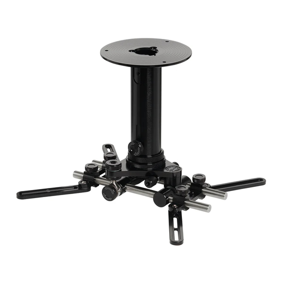
- Page 5 LIEFERUMFANG A) Montageplatte B) Hauptrohr (wahlweise lang oder kurz) C) Feststellschraube Höhenverstellung D) Teleskoprohr (wahlweise lang oder kurz) E) Projektor-Befestigungsarm F) Einstellung vertikale Neigung G) Fixierung Vor - Zurück H) Einstellung horizontale Rotation MONTAGEZUBEHÖR 4x Innensechskantschraube 4x Innensechskantschraube 4x Innensechskantschraube 3x Innensechskantschraube M4x20 mm M5x30 mm...
- Page 6 MONTAGE AN DER DECKE SCHRITT 1: BEFESTIGUNG DECKENMONTAGE Stellen Sie vor der Deckenmontage sicher, dass die Deckenkonstrukti- on die Projektor-Halterung inkl. al- len daran befestigten Geräten inkl. Zubehör tragen kann. Kunststoffdübel (5) 6x50 mm Schraubenkopfabdeckung (9) Universalschraube (7) Abb. 1: Bestigung Deckenmontage 2.
- Page 7 SCHRITT 2: MONTAGE DER EINZELTEILE 4. Entfernen Sie die Einstellungsein- heit und die Befestigungsarme von den runden Führungsschienen. Befestigen Sie die Einstellungseinheit mit den M5x40 Innensechskantschrau- Einstellung ben (4) an dem langen oder kurzen horizontale Teleskoprohr (D). Sollten die Schrau- Rotation benlöcher nicht übereinander passen, drehen Sie an der Einstellschraube (H...
- Page 8 Abb. 5: Montage der Halterung an den Projektor SCHRITT 4: ENDMONTAGE AN DER DECKE 7. Nachdem Sie die Befestigungsarme mit dem Projektor verbunden haben, schieben Sie das lange oder kurze Teleskoprohr (D) in das bereits an die Decke montierte Hauptrohr (B). (Wenn Sie sich für die kurze Variante entschieden ha- ben, schrauben Sie den Zierring und die Feststellschraube vom langen Haupt- rohr ab und nutzen Sie diese für das kurze Hauptrohr.) Ziehen Sie anschließend die Feststellschraube zur Höhenverstellung (C) fest an.
- Page 9 SCHRITT 6: EINSTELLUNG/AUSRICHTUNG DER HALTERUNG Vor und Zurück Sie können den Projektor an der Halterung auf einer Achse vor und zurück bewegen. Lösen Sie hierzu die Stellschrauben und bewegen den Projektor entlang der Führungsschienen vor oder zurück. Ziehen Sie anschließend die Schrauben wieder fest.
- Page 10 Teleskoprohr ein wenig und ziehen ihn anschließend wieder fest. ANSICHT HÖHE MIT STANDARD TELESKOPROHR min.: 285 mm max.: 430 mm ANSICHT HÖHE MIT KURZEM FIXEM TELESKOPROHR Maximale Belastung OMG Halterung: 30 kg fi x: 135 mm celexon Europe GmbH | Gutenbergstraße 2 | 48282 Emsdetten | DE...
- Page 11 Operating instructions celexon projector ceiling mount MultiCel LuxusLine OMG-1000 Thank you for purchasing this product. For optimum performance and safety, please read these instructions carefully before connecting or operating this product. Please retain these instructions for future use. Version: 32423_031...
- Page 12 Contact the dealer immediately, from whom you purchased the product or celexon directly (Web: www.celexon.co.uk, Mail: info@celexon.co.uk) for further information.
- Page 13 Incorrect installation or use may also invalidate the warranty. • If you are unsure about the use of the product, please contact your specialist personnel, your dealer or celexon directly (Web: www.celexon.co.uk, Mail: info@celexon.co.uk).
-
Page 14: Care Instructions
• Technical changes and errors excepted. The manufacturer accepts no responsibility for damage to property or personal injury, if the bracket is used outside the recommended specifications, or in the event of impro- per installation. DISCLAIMER The information in this document is subject to change without notice by the manufactu- rer. -
Page 15: Package Contents
MOUNT OVERVIEW A) Mounting plate B) Main tube (optionally long or short) C) Locking screw for height adjustment D) Telescopic tube (optionally long or short) E) Projector mounting arm F) Vertical tilt adjustment G) Forward - backward fixation H) Horizontal rotation adjustment PACKAGE CONTENTS 4x Hexagon socket screw 4x Hexagon socket screw... - Page 16 MOUNTING ON THE CEILING STEP 1: CEILING MOUNTING 1. Before installing the ceiling, make sure that the ceiling construction sup- ports the projector mount incl. all atta- ched devices incl. accessories. Plastic dowel (5) 6x50 mm Universal screw Screw head cover (9) Fig.
- Page 17 STEP 2: ASSEMBLY OF THE INDIVIDUAL PARTS 4. Remove the adjustment unit and the fi xing arms from the round guide rails. Secure the adjustment unit with the M5x40 hexagon socket screws (4) to the long or short telescopic tube (D). Setting If the screw holes do not fi t over each horizontal...
- Page 18 Fig. 5: Mounting the bracket to the projector STEP 4: FINAL ASSEMBLY ON THE CEILING 7. After you have connected the mounting arms to the projector, slide the long or short telescopic tube (D) into the main tube (B) that has already been mounted on the ceiling.
- Page 19 STEP 6: ADJUSTMENT/ALIGNMENT OF THE BRACKET Back and forth You can move the projector back and forth on the bracket on one axis. To do this, loosen the adjusting screws and move the projector backwards or for- wards along the guide rails. Then tighten the screws again. Adjusting screw linear movement Settings...
- Page 20 SIDE VIEW HEIGHT WITH STANDARD TELESCOPIC TUBE min.: 285 mm max.: 430 mm SIDE VIEW WITH SHORT FIXED TUBE Maximum load of the OMG bracket: 30 kg fi x: 135 mm celexon Europe GmbH | Gutenbergstraße 2 | 48282 Emsdetten | DE...
- Page 21 Notice d’utilisation Support de plafond celexon pour vidéoprojecteur MultiCel LuxusLine OMG-1000 Merci d’avoir choisi ce produit. Pour une performance et une sécurité optimales, veuillez lire attentivement les présentes instructions avant d’installer ou d’utiliser ce produit. Veuillez conserver la présente notice pour une consultation ultérieure.
- Page 22 Si vous constatez des dommages extérieurs sur l’appareil ou des fonc- tionnements inattendus ou inhabituels, cessez d’utiliser le produit. Contactez immé- diatement le revendeur auprès duquel vous avez acheté le produit ou directement celexon (web : www.celexon.fr, mail : info@celexon.fr) pour de plus amples informa- tions. •...
- Page 23 • Après le montage du produit et des autres composants, il convient de vérifier que leur résistance et leur sécurité de fonctionnement sont suffisantes. • La résistance et la capacité admissible des charges suspendues doivent être contrô- lées au moins deux fois par an. •...
-
Page 24: Exclusion De Responsabilité
Une installation ou une utilisation incorrecte peut entraîner l’annulation de la garantie. • Si vous n’êtes pas sûr lors de l’utilisation du produit, contactez le person- nel spécialisé, votre revendeur ou directement celexon (Web : www.celexon.fr, Mail : info@celexon.fr). • Sous réserve de modifications techniques et d’erreurs. -
Page 25: Contenu De La Livraison
CONTENU DE LA LIVRAISON A) Plaque de montage B) Tube principal (long ou court, au choix) C) Vis de blocage du réglage de la hauteur D) Tube télescopique (long ou court, au choix) E) Bras de fixation du projecteur F) Réglage de l’inclinaison verticale G) Fixation avant - arrière H) Réglage de la rotation horizontale ACCESSOIRES DE MONTAGE... - Page 26 MONTAGE AU PLAFOND ÉTAPE 1 : FIXATION DU MONTAGE AU PLAFOND Avant de procéder au montage au plafond, assurez-vous que la struc- ture du plafond puisse supporter le support du projecteur, ainsi que tous les appareils qui y sont fi xés, accessoires inclus.
- Page 27 ÉTAPE N°2 : MONTAGE DES PIÈCES DÉTACHÉES 4. Retirez l’unité de réglage et les bras de fi xation des rails de guidage ronds. Fixez l’unité de réglage sur le tube té- lescopique long ou court (D) à l’aide des vis à six pans creux M5x40 (4). Si Réglage les trous des vis ne se superposent pas, rotation...
- Page 28 Fig. 5 : Montage du support sur le projecteur ÉTAPE N°4 : MONTAGE FINAL AU PLAFOND 7. Après avoir connecté les bras de fi xation au projecteur, insérez le tube té- lescopique long ou court (D) dans le tube principal (B) déjà monté au plafond. (Si vous avez opté...
- Page 29 ÉTAPE N°6 : RÉGLAGE/ORIENTATION DU SUPPORT Avant et arrière Vous pouvez déplacer le projecteur d'avant en arrière sur un axe du support. Pour ce faire, desserrez les vis de réglage et déplacez le projecteur vers l’avant ou l’arrière le long des rails de guidage. Resserrez ensuite les vis. Vis de réglage mouvement linéaire...
- Page 30 HAUTEUR DE VUE AVEC TUBE TÉLESCOPIQUE STANDARD min. : 285 mm max. : 430 mm HAUTEUR DE VUE AVEC TUBE TÉLESCOPIQUE FIXE COURT Charge maximale du support OMG : 30 kg Fixe : 135 mm celexon Europe GmbH | Gutenbergstraße 2 | 48282 Emsdetten | DE...
- Page 31 Manual de instrucciones Soporte de techo para proyector MultiCel LuxusLine OMG-1000 celexon Gracias por adquirir este producto. Para un rendimiento y seguridad óptimos, lea atentamente estas instrucciones antes de instalar o utilizar este producto. Conserve estas instrucciones para futuras consultas.
- Page 32 Si observa algún daño externo en el dispositivo o un funcionamiento inespe- rado o inusual, deje de utilizar el producto. Póngase en contacto inmediatamente con el distribuidor al que compró el producto o directamente con celexon (web: www.celexon.es correo: info@celexon.es) para obtener más información.
- Page 33 al menos dos veces al año. • No cargue el producto con más peso del permitido. Observe la carga máxima per- mitida. • Asegúrese de centrar la carga en el producto, especialmente una vez se haya ajus- tado. • Las líneas y cables de suministro de su proyector no deben estar sometidos a cargas y deben disponerse de forma que no sufran daños ni aplastamientos.
-
Page 34: Exención De Responsabilidad
• Si no está seguro de cómo utilizar el producto, póngase en contacto con personal cualificado, con su distribuidor o directamente con celexon (web: www.celexon.es correo: info@celexon.es). • Salvo cambios y errores técnicos. El fabricante no acepta ninguna responsabilidad por daños materiales o personales si el soporte se utiliza fuera de las especificaciones recomendadas, o si se instala incorrec- tamente. - Page 35 VOLUMEN DE SUMINISTRO A) Placa de montaje B) Tubo principal (a elegir entre largo o corto) C) Tornillo de regulación de altura D) Tubo telescópico (a elegir entre largo o corto) E) Brazo de fijación del proyector F) Ajuste de la inclinación vertical G) Fijación delante - detrás H) Ajuste de la rotación horizontal ACCESORIOS DE MONTAJE...
- Page 36 MONTAJE EN EL TECHO PASO 1: FIJACIÓN PARA MONTAJE EN TECHO Antes del montaje en el techo, ase- gúrese de que la construcción del techo pueda aguantar el peso del soporte del proyector junto con todos los dispositivos y accesorios que han de fi jarse.
- Page 37 PASO 2: MONTAJE DE LAS PIEZAS INDIVIDUALES 4. Desmonte la unidad de ajuste y el brazo de fi jación de los rieles guía re- dondos. Fije la unidad de ajuste con los tornillos Allen M5x40 (4) al tubo telescópico lar- Ajuste de la go o corto (D).
- Page 38 Fig. 5: montaje del soporte en el proyector PASO 4: MONTAJE FINAL EN EL TECHO 7. Después de haber unido los brazos de fi jación al proyector, deslice el tubo telescópico largo o corto (D) por el tubo principal ya montado en el techo (B). (Si ha elegido la versión corta, desenrosque el anillo embellecedor y el tornillo de fi jación del tubo principal largo y utilícelos para la variante corta).
- Page 39 PASO 6: AJUSTE/ORIENTACIÓN DEL SOPORTE Hacia delante y hacia atrás Puede desplazar el proyector hacia delante en el soporte y hacia atrás sobre un eje. Para ello, afl oje los tornillos de ajuste y desplace el proyector hacia de- lante y hacia atrás a lo largo de los rieles guía. A continuación, vuelva a apretar los tornillos.
- Page 40 VISTA DE ALTURA CON TUBO TELESCÓPICO ESTÁNDAR mín.: 285 mm máx.: 430 mm VISTA DE ALTURA CON TUBO TELESCÓPICO CORTO FIJO Carga máxima del soporte OMG: 30 kg fi jo: 135 mm celexon Europe GmbH | Gutenbergstraße 2 | 48282 Emsdetten | DE...
- Page 41 Manuale di istruzioni Supporto a soffi tto per proiettore celexon MultiCel LuxusLine OMG-1000 Grazie per aver acquistato questo prodotto. Per garantire prestazioni e sicurezza ottimali, leggere attentamente le presenti istruzioni prima di collegare o utilizzare il supporto a soffi tto per proiettore. Conservare queste istruzioni per riferimenti futuri.
- Page 42 Contattare immediatamente il rivenditore presso il quale è stato acqui- stato il prodotto o contattare direttamente celexon (sito: www.celexon.it, e-mail: info@celexon.it) per ulteriori informazioni.
- Page 43 Il montaggio o l’utilizzo non corretti del supporto potrebbero far decadere la garanzia. • In caso di incertezze sull’uso del supporto, rivolgersi al personale spe- cializzato, rivenditore direttamente celexon (sito: www.celexon.it, e-mail: info@celexon.it).
-
Page 44: Esclusione Di Responsabilità
• Con riserva di modifiche tecniche e salvo errori di stampa. Il produttore non si assume alcuna responsabilità per danni a cose o persone se il sup- porto viene utilizzato al di fuori delle specifiche raccomandate o se viene installato in modo non corretto. -
Page 45: Contenuto Della Fornitura
CONTENUTO DELLA FORNITURA A) Piastre di montaggio B) Tubo principale (a scelta lungo o corto) C) Vite per la regolazione dell’altezza B) Tubo telescopico (a scelta lungo o corto) E) Braccio di montaggio del proiettore F) Regolazione dell'inclinazione verticale G) Il fissaggio in avanti - indietro H) Impostazione della rotazione orizzontale ACCESSORI DI MONTAGGIO 4 viti a esagono incassato... - Page 46 MONTAGGIO AL SOFFITTO PASSAGGIO 1: FISSAGGIO AL SOFFITTO Prima di procedere al montaggio, assicurarsi che il soffi tto sia in gra- do di sostenere il supporto del pro- iettore, compreso l’apparecchio e gli accessori ad esso collegati. Tassello di plastica Vite universale Tappo di copertura (9) 6x50 mm (7)
- Page 47 PASSAGGIO 2: MONTAGGIO DEI SINGOLI COMPONENTI 4. Rimuovere l’unità di regolazione e i bracci di fi ssaggio dalle guide circolari. Fissare l’unità di regolazione al tubo telescopico lungo o corto (D) con le Imposta- viti a brugola M5x40 (4). Se i fori del- zione della le viti non sono allineati, girare la vite rotazione...
- Page 48 Fig. 5: Montaggio del supporto al proiettore PASSAGGIO 4: MONTAGGIO FINALE AL SOFFITTO 7. Dopo aver fi ssato i bracci di montaggio al proiettore, inserire il tubo telesco- pico lungo o corto (D) nel tubo principale (B) già montato sul soffi tto (se si è optato per la versione corta, svitare l’anello ornamentale e la vite di bloccaggio dal tubo principale lungo e utilizzarli per il tubo principale corto).
- Page 49 PASSAGGIO 6: REGOLAZIONE/ALLINEAMENTO DEL SUPPORTO Avanti e indietro Si può spostare il proiettore in avanti e indietro lungo un asse del supporto. A tale scopo, allentare le viti di regolazione e spostare il proiettore in avanti o indietro lungo le guide. In seguito, serrare di nuovo le viti. Viti di regolazione del movimento lineare...
- Page 50 VISTA IN ALTEZZA CON TUBO TELESCOPICO STANDARD min: 285 mm max: 430 mm VISTA IN ALTEZZA CON TUBO TELESCOPICO FISSO CORTO Carico massimo del suppor- to OMG: 30 kg fi sso: 135 mm celexon Europe GmbH | Gutenbergstraße 2 | 48282 Emsdetten | DE...
- Page 51 Instrukcja obsługi Uchwyt sufi towy na projektor celexon MultiCel LuxusLine OMG-1000 Dziękujemy za zakup tego produktu. Aby zapewnić optymalne działanie i bezpieczeństwo, przed zainstalowaniem lub obsłu- gą tego produktu należy uważnie przeczytać niniejszą instrukcję. Prosimy o zachowanie niniejszej instrukcji do wykorzystania w przyszłości.
-
Page 52: Wskazówki Ostrzegawcze
Jeśli widoczne są zewnętrzne uszkodzenia urządzenia albo w przypadku stwierdzenia niespodziewanego lub nietypowego sposobu działa- nia nie wolno dalej używać produktu. Należy bezzwłocznie skontaktować się ze sprzedawcą, u którego nabyto produkt lub bezpośrednio z firmą celexon (Internet: www.celexon.pl, e-mail: info@celexon.pl), aby uzyskać więcej informacji. •... - Page 53 (Internet: www.celexon.pl, e-mail: info@celexon.pl). • Zastrzega się możliwość zmian technicznych i błędów. Producent nie ponosi odpowiedzialności za szkody materialne lub obrażenia ciała, jeśli uchwyt będzie używany niezgodnie z zalecanymi specyfikacjami lub jeśli będzie on nie- prawidłowo zainstalowany.
-
Page 54: Wyłączenie Odpowiedzialności
WYŁĄCZENIE ODPOWIEDZIALNOŚCI Informacje zawarte w tym dokumencie mogą ulec zmianie bez uprzedniego powiado- mienia ze strony producenta. Zmiany będą dodawane do kolejnych wersji niniejszej in- strukcji. Producent nie udziela gwarancji ani rękojmi odnośnie poprawności informacji zawartych w tym dokumencie. WSKAZÓWKI DOTYCZĄCE PIELĘGNACJI Uchwyt należy czyścić... -
Page 55: Zakres Dostawy
ZAKRES DOSTAWY A) Płyta montażowa B) Rura główna (do wyboru długa lub krótka) C) Śruba ustalająca do regulacji wysokości B) Rura teleskopowa (do wyboru długa lub krótka) E) Ramię mocujące projektora F) Ustawienie nachylenia pionowego G) Mocowanie do przodu - do tyłu H) Ustawianie obrotu poziomego AKCESORIA MONTAŻOWE 4 śruby imbusowe M4x20... - Page 56 MONTAŻ NA SUFICIE KROK 1: MOCOWANIE NA SUFICIE Przed montażem na sufi cie upew- nić się, że konstrukcja sufi tu unie- sie uchwyt projektora wraz ze wszystkimi zamocowanymi nim urządzeniami, w tym akceso- riami. kołek z tworzywa sztucznego (5) śruba uniwersalna osłona łba śruby (9) 6x50 mm Rys.
- Page 57 KROK 2: MONTAŻ POSZCZEGÓLNYCH CZĘŚCI 4. Usunąć jednostkę regulacyjną i ra- miona mocujące z okrągłych szyn pro- wadzących. Zamocować jednostkę regulacyjną śrubami imbusowymi M5x40 (4) na długiej lub krótkiej rurze teleskopowej ustawianie (D). Jeśli otwory na śruby nie pasują do obrotu poziomego siebie, należy obrócić...
- Page 58 Rys. 5: Montaż uchwytu na projektorze KROK 4: MONTAŻ KOŃCOWY NA SUFICIE 7. Po połączeniu ramion mocujących z projektorem wsunąć długą lub krótką rurę teleskopową (D) w rurę główną (B) już zamontowaną na sufi cie. (W przy- padku wybrania wariantu krótkiego należy odkręcić pierścień ozdobny i śrubę ustalającą...
- Page 59 KROK 6: USTAWIENIE/WYRÓWNANIE UCHWYTU Do przodu i do tyłu Projektor na uchwycie można przemieszczać na osi do przodu i do tyłu. W tym celu należy odkręcić śruby nastawcze i przemieścić projektor wzdłuż szyn pro- wadzących do przodu lub do tyłu. Następnie ponownie dokręcić śruby. śruba nastawcza ruchu liniowego ustawienia...
- Page 60 WIDOK ZAKRESU REGULACJI WYSOKOŚCI ZE STANDARDOWĄ RURĄ TELESKOPOWĄ min.: 285 mm maks.: 430 mm WIDOK ZAKRESU REGULACJI WYSOKOŚCI Z KRÓTKĄ, STAŁĄ RURĄ TELESKOPOWĄ Maksymalne obciążenie uchwytu OMG: 30 kg stale: 135 mm celexon Europe GmbH | Gutenbergstraße 2 | 48282 Emsdetten | DE...
- Page 61 Bedieningshandleiding celexon Beamer-plafondhouder MultiCel LuxusLine OMG-1000 Hartelijk dank voor uw aankoop van dit product. Voor optimale prestaties en veiligheid moet u deze aanwijzingen zorgvuldig doorlezen voordat u dit product installeert of gebruikt. Bewaar deze handleiding voor later gebruik. Versie: 32423_031...
- Page 62 Neem onmiddelijk contact op met de dealer bij wie u het product hebt gekocht of rechtstreeks met celexon (web: www.celexon.nl, mail: info@celexon.nl) voor verdere informatie.
- Page 63 Let erop dat de ondergrond voldoende draagvermogen heeft om het product incl. verdere componenten veilig en blijvend te dragen.Na de montage van het product en verdere componenten moeten deze op voldoende stevigheid en gebruiksveilig- heid worden gecontroleerd. • Hangende lasten moeten minimaal twee keer per jaar op vastzitten en draagvermo- gen worden gecontroleerd.
-
Page 64: Uitsluiting Van Aansprakelijkheid
• Als u onzeker bent over het gebruik van het product, neem dan rechtstreeks contact op met gekwalificeerd personeel, uw dealer of celexon (website: www.celexon.nl, E-mail: info@celexon.nl). • Technische wijzigingen en vergissingen voorbehouden. De fabrikant is niet aansprakelijk voor materiële schade of letsel als de houder buiten de aanbevolen specificaties wordt gebruikt of onoordeelkundig geïnstalleerd is. - Page 65 LEVERINGSOMVANG A) Montageplaat B) Hoofdbuis (naar keuze lang of kort) C) Borgschroef hoogteverstelling B) Telescopische buis (naar keuze lang of kort) E) Projectorbevestigingsarm F) Instelling verticale hellingshoek G) Fixatie vooruit - achteruit H) Instelling horizontale rotation MONTAGETOEBEHOREN 4x inbusschroef M4x20 mm 4x inbusschroef M5x30 mm 4x inbusschroef M6x30 mm 3x inbusschroef M5x40 mm...
- Page 66 MONTAGE AAN HET PLAFOND STAP 1: BEVESTIGING PLAFONDMONTAGE Voordat u de projector aan het pla- fond monteert, moet u zich ervan verzekeren dat de plafondstructuur de projectorhouder kan ondersteu- nen, inclusief alle apparaten en ac- cessoires die eraan zijn bevestigd. Kunststof pluggen (5) 6x50mm Schroefkopafdekking (9)
- Page 67 STAP 2: MONTAGE VAN DE AFZONDERLIJKE ONDERDELEN 4. Verwijder de instellingseenheid en de montagearmen van de ronde gelei- derails. Bevestig instellingseenheid de lange of korte telescopische buis Instelling (D) met behulp van de M5x40 inbus- horizontale schroeven (4). Als de schroefgaten rotation niet op elkaar passen, draait u de stel- schroef (H - horizontale rotatie) totdat...
- Page 68 Afb. 5: Montage van de houder aan de projector STAP 4: UITEINDELIJKE MONTAGE AAN HET PLAFOND 7. Nadat u de bevestigingsarmen aan de projector hebt bevestigd, schuift u de lange of korte telescoopbuis (D) in de hoofdbuis (B) die al aan het plafond is gemonteerd.
- Page 69 STAP 6: INSTELLING/UITLIJNING VAN DE HOUDER Vooruit en achteruit U kunt de projector op een as heen en weer bewegen aan de houder. Om dit te doen, draait u de stelschroeven los en beweegt u de projector heen of weer langs de geleiderails.
- Page 70 AANZICHT HOOGTE MET STANDAARD TELESCOOPBUIS min.: 285 mm max.: 430 mm AANZICHT HOOGTE MET KORTE VASTE TELESCOOPBUIS Maximale belasting van de OMG-houder: 30 kg vast: 135 mm celexon Europe GmbH | Gutenbergstraße 2 | 48282 Emsdetten | DE...
- Page 71 Bruksanvisning celexon projektorfäste för innertak MultiCel LuxusLine OMG-1000 Tack för att du har valt denna produkt! Läs igenom denna bruksanvisning noga innan du installerar eller använder denna pro- dukt för att garantera säkerheten och uppnå bästa möjliga prestanda. Spara denna bruksanvisning för framtida bruk.
- Page 72 Om du hittar utvändiga skador på enheten eller om den inte fungerar som den ska eller om den beter sig onormalt får produkten inte längre användas. Kontakta ome- delbart återförsäljaren som du köpte produkten av eller vänd dig direkt till celexon (webbplats: www.celexon.se, e-post: info@celexon.se) för ytterligare information.
- Page 73 är ansluten till den. Felaktig installation eller felaktig användning även leda till garantin upphör att gälla. • Om du är osäker på hur produkten ska användas ber vi dig kontakta fack- personal, din återförsäljare eller celexon direkt (webbplats: www.celexon.se, e-post: info@celexon.se).
- Page 74 • Med reservation för tekniska ändringar och fel. Tillverkaren ansvarar inte för sakskador eller personskador som uppstår om fästet inte används enligt de rekommenderade specifikationerna eller om installationen är felaktigt utförd. ANSVARSFRISKRIVNING Informationen i detta dokument kan ändras av tillverkaren utan förvarning. Ändringar införs i de efterföljande versionerna av denna bruksanvisning.
- Page 75 LEVERANSOMFATTNING A) Monteringsplatta B) Huvudrör (valfritt långt eller kort) C) Låsskruv höjdjustering D) Teleskoprör (valfritt långt eller kort) E) Projektor fästarm F) Inställning vertikal lutning G) Fixering fram – tillbaka H) Inställning horisontell rotation MONTERINGSTILLBEHÖR 4 insexskruvar M4 x 20 mm 4 insexskruvar M5 x 30 mm 4 insexskruvar M6 x 30 mm 3 insexskruvar M5 x 40 mm...
- Page 76 MONTERING PÅ INNERTAKET STEG 1: FASTSÄTTNING MONTERING PÅ INNERTAK Innan du monterar på innertaket, se till att innertakets konstruktion kan bära projektorfästet inklusive alla enheter och tillbehör som är fastsatta på detta. Plastplugg (5) 6 x 50 mm Kåpa till skruvhuvud (9) universalskruv (7) Bild 1: Fastsättning montering på...
- Page 77 STEG 2: MONTERING AV ENSKILDA DELAR 4. Ta bort inställningsenheten och monteringsarmarna från de runda styr- skenorna. Fäst inställningsenheten på det långa eller korta teleskopröret (D) med Inställning M5 x 40 insexskruvarna (4). Om skruv- horisontell hålen inte är i linje, vrid justerskruven rotation (H –...
- Page 78 Bild 5: Montering av fästet på projektorn STEG 4: SLUTMONTERING PÅ INNERTAKET 7. Efter anslutning av monteringsarmarna till projektorn skjut in det långa eller korta teleskopröret (D) i huvudröret (B) som redan har monterats på innerta- ket. (Om du har valt den korta versionen, skruva loss dekorringen och låsskru- ven från det långa huvudröret och använd dem för det korta huvudröret.) Dra därefter åt låsskruven för höjdjustering (C) hårt.
- Page 79 STEG 6: INSTÄLLNING/INRIKTNING AV FÄSTET Fram och tillbaka Du kan fl ytta projektorn fram och tillbaka på en axel när den sitter fast på fäs- tet. För detta ändamål lossa justerskruvarna och fl ytta projektorn fram eller tillbaka längs styrskenorna Dra sedan åt skruvarna igen. Justerskruv linjär rörelse Inställningar...
- Page 80 åt den igen. VY HÖJD MED STABDARD TELESKOPRÖR min.: 285 mm max.: 430 mm VY HÖJD MED KORT FAST TELESKOPRÖR Max. belastning för OMG-fäs- tet: 30 kg fast: 135 mm celexon Europe GmbH | Gutenbergstraße 2 | 48282 Emsdetten | DE...
Need help?
Do you have a question about the MultiCel LuxusLine OMG-1000 and is the answer not in the manual?
Questions and answers