Advertisement
Quick Links
Operating instructions
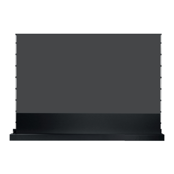
celexon UST High Contrast Floor
Rising screen - HomeCinema Plus
Thank you for purchasing this product.
For optimum performance and safety, please read these instructions carefully before
connecting or operating this product. Please retain these instructions for future reference.
Version: 32422_112
Advertisement

Related Manuals for Celexon HomeCinema Plus


Summary of Contents for Celexon HomeCinema Plus
- Page 1 Operating instructions celexon UST High Contrast Floor Rising screen - HomeCinema Plus Thank you for purchasing this product. For optimum performance and safety, please read these instructions carefully before connecting or operating this product. Please retain these instructions for future reference.
- Page 2 Contact the dealer immediately from whom you purchased the product or celexon directly (Web: www.celexon.co.uk, Mail: info@celexon.co.uk) for further information.
- Page 3 Incorrect installation or use may also invalidate the warranty. • If you are unsure about the use of the product, please contact your specia- list personnel, your dealer or celexon directly (Web: www.celexon.co.uk, Mail: info@celexon.co.uk). • Technical changes and errors excepted.
- Page 4 IMPORTANT NOTES ON FABRIC CLEANING AND CARE Do not use a cloth for cleaning! This screen surface material is particularly sensitive to contact with hands or greasy moist objects. This is due to the surface structure, which is what makes this high-contrast ultra-short distance screen work.
-
Page 5: Product Overview
PRODUCT OVERVIEW Tension rod Joint Upper arm Rope tensioning system Projection screen Joint Lower arm Flap Side cap Housing Transport handle Operating button Spring joint IR Eye connection (3.5 mm) Power connection 12V Trigger connector (2.5 mm) Side View... -
Page 6: Technical Data
IN THE BOX 1x Power cable 1x Infrared remote control 1x Radio remote control 1x Trigger cable (IR) (RF) 2x Adjustable mounting 1x Adjustment tool (4 mm) 1x Allen key 6x M5 x 14 mm threaded bracket with mounting screw plate 10x M5 x 10 mm threaded 1x Cleaning brush for pro-... -
Page 7: Installation Notes
INSTALLATION NOTES Install the screen in a position that is clearly visible to all viewers. The optimal installation height corresponds to the position of the viewers when the screen is extended: eye level = lower third of the screen surface. Install the screen in a straight and level position, otherwise there is a risk of the screen fabric being wound up and unwound crookedly. - Page 8 MOUNTING ON THE WALL OR ON A FURNITURE BACK PANEL Mark an „installation line“ at the height where the screen is to be positioned la- ter. The „installation line“ corresponds to the lower edge of the screen housing. Mark the centre of the screen on the installation line (Fig.1). The distance of the two mounting brackets (centre to centre of the brackets!) must be 1,600 mm.
- Page 9 Adjustable +-1.5° Adjustable +-1.5° Adjustable +-1.5° Furniture Furniture Adjustable +-1.5° M5 x 14 mm Threaded screw Installation 1 Installation 2 Installation 3 Installation 4 Fig. 2 Attach the mounting brackets to your solid concrete or solid stone wall with the 4 screws (5x40 mm) and 4 dowels each (Fig. 1) For other load-bearing structures, obtain suitable mounting accessories! If you are unsure, ask a speci- alist dealer about the correct and safe attachment to your supporting structure (e.g.
- Page 10 then hand-tighten the screws to secure the screen against falling down. (Fig. 2) Note: For installation methods 1 and 2 the mounting plate (b) is not needed and should be removed. Fig. 3 INSTALLATION OF THE SCREEN (HANGING WITH MOUNTING PLATE) For installation methods 3 and 4 first attach the additional mounting (b, Fig.
- Page 11 Now that the screen is in its final pla- ce on the brackets, connect the power supply to the screen and extend com- pletely. Now check the angle between the screen and your wall and use the Allen key to adjust the adjustment screws on the two L-brackets until the fabric is perfectly straight and parallel to the wall.
-
Page 12: Operation
OPERATION This screen has 4 control options: Housing push-button, manual switching cycle. Trigger control Radio remote control Infrared remote control CONTROL VIA THE HOUSING PUSH BUTTONS WITH MANUAL SWITCHING CYCLE The manual cycle button is located on the end cover of the power supply side of the housing. - Page 13 Alternatively, you can purchase an optional wireless trigger or a jack trigger cable from celexon. Optional jack trigger cable: Only possible if your projector is equipped with a Trigger Out connector. The trigger function must be activated in the pro- jector‘s menu and the projector should comply with the trigger standards of...
- Page 14 With the radio remote control, the screen can also be reliably controlled if it is installed in a piece of furniture and a clear view of the infra-red eye is not possible or desired. Please note: The radio remote control can also control units through walls (i.e. from other rooms) but you will not have a view of the screen to control the extension or retraction.
- Page 15 CODE LINKING/DELETING THE RADIO REMOTE CONTROL The code pairing of the radio remote control has already been successfully completed at the factory. (Info: The infrared remote control does not generally have to be paired.) To disconnect the screen from the mains for 10 seconds and then reconnect it to the mains.
- Page 16 The default black drop is set at 350 mm and should NOT be outside of 300 - 400 mm in order not to negatively influence the flatness. • Contact celexon if you have any questions about this setting, before chan- ging the factory default setting.
- Page 17 Should the spring condition be overstretched due to such an inci- dent and the flap no longer closes fully or opens too far, contact celexon for in- Overstretched structions on how to replace the spring. condition Spring-loaded hinge flap opening/closing...
- Page 18 Flatness of the fabric: • The black drop must be in the range of min. 250 mm - max. 400 mm. to maintain the flatness. • Do not change the feed on the motor, as this will change the digital setting that controls the extension height and may permanently adjust or damage your product.
- Page 19 • If you want to place the screen and your projector on a sideboard that hangs freely on the wall, you must make absolutely sure that the wall is adequate for the additional load!
- Page 20 UST High Contrast Floor Rising screen - HomeCinema Plus Hereby celexon Europe GmbH declares that the celexon CLR HomeCinema UST Electric Floor High Contrast Screen complies with the directive 2014/53/ EU. The EU declaration of conformity can be downloaded from the following ad- dress: www.celexon.de/zertifikate...
- Page 21 UST High Contrast Floor Rising screen - HomeCinema Plus Hereby celexon Europe GmbH declares that the radio equipment type celexon CLR HomeCinema UST Electric Floor High Contrast Screen complies with the Radio Equipment Regulations 2017. The UK declaration of conformity can be downloaded from the following address: www.celexon.de/zertifikate...
Need help?
Do you have a question about the HomeCinema Plus and is the answer not in the manual?
Questions and answers