Table of Contents
Advertisement
Quick Links
Gate Swings Evenly and Freely
Post Bracket
Hung Firmly and Plumb
Secondary Opener
Power Cable
Fence Post Set in Concrete
This product meets the requirements of UL325, the standard for gate operator safety.
Mighty Mule
is the retail brand of Nortek Security and Control, LLC.
®
Copyright
©
2019 Nortek Security and Control, LLC.
Installation Manual
(For a single or dual gate installation)
Warning Sign
Gate Bracket
Gate Bracket
Horizontal Support
Horizontal Support
PVC conduit (not included)
to run second opener power
cable under driveway.
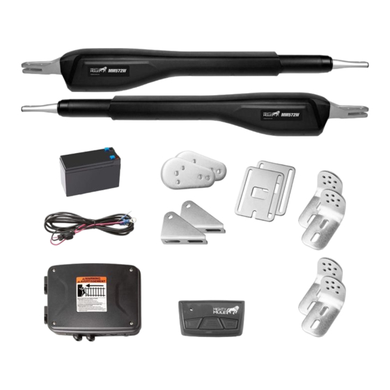
Dual gate installation MM572W]
Example of Dual Gate finished installation
(Installations vary slightly on different types of gates)
MM571W
MM572W
Single gate installation [MM571W]
Post Bracket
Warning Sign
Primary Gate Opener
Fence Post Set in Concrete
PVC conduit (not included)
to protect wire from lawn
mowers and weed eaters.
Control Box
120 Volt indoor
Transformer
(surge protector
not supplied)
Run 1000' (max.) of low voltage
wire to control box from
transformer (wire not included).
10022116 A
Advertisement
Table of Contents

Related Manuals for Nortek Security & Control MIGHTY MULE MM571W


Summary of Contents for Nortek Security & Control MIGHTY MULE MM571W
- Page 1 MM571W MM572W Installation Manual (For a single or dual gate installation) Single gate installation [MM571W] Post Bracket Gate Swings Evenly and Freely Post Bracket Control Box Hung Firmly and Plumb Warning Sign Warning Sign 120 Volt indoor Primary Gate Opener Secondary Opener Transformer Gate Bracket...
-
Page 2: Table Of Contents
Table of Contents WARNING Please Read This First! .......................... ii Important Safety Information ........................ iii This equipment meets Underwriters Laboratory Standard 325 (UL 325). However, gate equipment has Manually Opening and Closing Gate ..............................iii hazards associated with its use and therefore by installing this product the installer and user accept For the Installer and End User ................................ -
Page 3: Please Read This First
Please Read This First! Important Safety Information Thank you for purchasing a Mighty Mule Gate Operator— The Mighty Mule Gate Operator also has an adjustable Because automatic gate operators produce high levels be completely exhaustive in nature. It does, however, Nortek Security and Control's "do-it-yourself"... -
Page 4: Important Safety Information
Important Safety Information Important Safety Information FOR THE INSTALLER AND END USER FOR THE INSTALLER AND END USER WARNING Typical Entrapment Zones are shown in the diagrams on page Zone 1 – leading edge of the gate and the fence post. To reduce the risk of injury or death: Zone 2 –... - Page 5 Important Safety Information Important Safety Information FOR THE INSTALLER AND END USER FOR THE INSTALLER AND END USER Mighty Mule gate operators utilize Dual Sense Technology One or more edge sensors may be located at the leading ™ III. After Installation 11.
- Page 6 Important Safety Information Important Safety Information INSTALLING WARNING SIGNS AND PEDESTRIAN GATES REQUIRED SAFETY PRECAUTIONS FOR GATES Warning signs alert people of automatic gate operation and are required when installing Mighty Mule Automatic Gate These warning labels should be found at the locations specified below. If any of them are missing, immediately contact Operators.
-
Page 7: Technical Specifications
Before You Begin Technical Specifications POWERING OPTIONS MIGHTY MULE 571W/572W GATE OPENER Determine Charging Option for Battery: Transformer OR Solar • Low friction screw drive (linear actuator) rated for -5 ºF to +160 ºF (-20 ºC to +71 ºC). • Opener length with push-pull tube fully retracted is 40.25", mounting point to mounting point. -
Page 8: Important: Check For Proper Gate Installation
CHECK EXISTING GATE SIZE AND MATERIAL ITEMS INCLUDED FOR PRIMARY GATE OPENER INSTALLATION (MM571W) • Gate size: Up to 18 feet and up to 850 lbs. — See • Type of gate material: Vinyl, aluminum, chain link, Operational Capacity chart on page farm tube, wrought iron, wood. -
Page 9: Items Not Included
Mechanical Installation TOOLS NEEDED ASSESSING THE GATE FOR INSTALLATION 7/16” Bit Center Drill 1/2” Bit Punch 7/32” Bit Your gate operator can be mounted to a variety of gate types. This section shows some of the most common, along with the reinforcement methods recommended prior to or while mounting your gate operator. -
Page 10: Pull-To-Open Operator Mounting ( Most Common )
PULL-TO-OPEN OPERATOR MOUNTING ( MOST COMMON ) PULL-TO-OPEN OPERATOR MOUNTING Your Property Your Property Step 1 Step 3 ● Assemble the gate post bracket sub ● With the gate in the OPEN assembly as displayed. position, use clamps to secure the operator to the gate post and center cross member of the gate. - Page 11 PULL-TO-OPEN OPERATOR MOUNTING PULL-TO-OPEN OPERATOR MOUNTING Your Property Your Property Step 5 Step 8 ● Open the gate and reattach the operator to the gate ● Using a drill and 7/16” drill bit, bracket. drill the necessary holes to mount the gate post and gate ●...
-
Page 12: Installing The Closed Position Stop Plate / Pull-To-Open
PULL-TO-OPEN OPERATOR MOUNTING INSTALLING THE CLOSED POSITION STOP PLATE / PULL-TO-OPEN Your Property Your Property Step 1 Step 10 ● Remove the operator from the ● Secure the gate bracket with the gate post and gate brackets. supplied hardware as shown. ●... -
Page 13: Push-To-Open Operator Mounting
PUSH-TO-OPEN OPERATOR MOUNTING PUSH-TO-OPEN OPERATOR MOUNTING Your Property Your Property Post Bracket Assembly Step 1 Step 3 ● With the gate in the CLOSED position, use clamps to secure the ● Assemble the gate post bracket subassembly operator to the gate post and center as shown with the Push-to-Open pivot bracket cross member of the gate. - Page 14 PUSH-TO-OPEN OPERATOR MOUNTING PUSH-TO-OPEN OPERATOR MOUNTING Your Property Your Property Step 5 Step 8 ● Close the gate and reattach the operator to the ● Using a drill and 7/16” drill bit, drill the gate bracket. necessary holes to mount the gate post ●...
-
Page 15: Installing The Closed Position Stop Plate / Push-To-Open
PUSH-TO-OPEN OPERATOR MOUNTING INSTALLING THE CLOSED POSITION STOP PLATE / PUSH-TO-OPEN Your Property Your Property Step 10 Step 1 ● Secure the gate bracket with the ● Remove the operator from the gate post supplied hardware as shown. and gate brackets. ●... -
Page 16: Control Box Installation
CONTROL BOX INSTALLATION CONTROL BOX INSTALLATION Step 1 Step 4 ● If installing an optional second battery, connect the battery 4 ’ harness as shown in Step 3. ● Place the second battery and route harness as shown. ● Identify a suitable mounting location for your control box at least 3 ft. -
Page 17: Connecting The Operator(S) And Battery
CONNECTING THE OPERATOR(S) AND BATTERY CONNECTING THE OPERATOR(S) AND BATTERY Step 1 Step 3 ● Remove the sealing nut from one of ● Locate the PRIMARY operator wiring SEALING NUT the cable glands on the bottom of the terminals, and insert the wires into control box. -
Page 18: Transformer Or Solar Panel Wiring Installation
TRANSFORMER OR SOLAR PANEL WIRING INSTALLATION TRANSFORMER OR SOLAR PANEL WIRING INSTALLATION Step 3 WARNING Before digging contact local authorities to locate underground utilities such as electric and gas service. Step 1 1 2 3 4 5 1 2 3 4 5 RESET RESET AUTO... -
Page 19: Electrical Installation And Setup
Electrical Installation and Setup Step 4 TERM6 BAT+ DIP SWITCHES SETTINGS ● From the other end of the low voltage wire, BAT– 1 2 3 4 5 strip 1/2” from both the RED and BLACK RESET AUTO CLOSE wire. TERM6 Push/Pull-to-Open BAT+ ●... -
Page 20: Transmitter Programming
TRANSMITTER PROGRAMMING OPERATOR LIMIT SETTING Setting the Operator's Extended Limit (MM571W Only): 1. Press and hold the (up arrow) and (return/enter) buttons until LED1 turns on and the buzzer sounds. Release. 2. Use the (up arrow) and (down arrow) buttons to jog the gate operator to the EXTENDED position. 3. -
Page 21: Auto Close Setting
Connecting Additional Devices AUTO CLOSE SETTING Mighty Mule strongly recommends the use of additional obstruction detection devices however we do not endorse any specific Step 1 brand names. Only use products that are listed to be in compliance with any applicable UL safety standards and national and regional codes. -
Page 22: Control Board Connections
CONTROL BOARD CONNECTIONS CONNECTING ACCESSORIES NOTES: ● All ACCESSORY INPUTS (ITEMS 2-6) are dry contact,normally open inputs. DO NOT apply external voltage inputs to these terminals. ● All ACCESSORY INPUTS (ITEMS 2-6) are connected with respect to the COMMON terminals (ITEM 1). ... - Page 23 Maintenance Troubleshooting Guide - Audible Feedback ● Monthly, test the obstruction and entrapment protection systems. If your gate operator does not function properly after it is installed, use this guide before calling the Nortek Security and Control Service Department. ● Monthly, service the gate operator (make sure the power switch is OFF). Clean extended operator arm with a soft, dry clean cloth.
-
Page 24: Troubleshooting Guide - Visual Feedback
Troubleshooting Guide - Visual Feedback Audible Feedback Possible Diagnosis Check/Solution If your gate operator does not function properly after it is installed, use this guide before calling the Nortek Security and Control h Turn the system off and back on. Service Department. -
Page 25: For Your Records
For Your Records Visual Feedback Possible Diagnosis Check/Solution The unit will not run Unit arm travel (limits) not set. h Set travel limits Please record the product serial number (located on the right hand side of the control box), and the date and place of purchase in the h Program transmitter spaces provided below. -
Page 26: Repair Service
Repair Service If your Mighty Mule Gate Opener is not operating properly, please follow the steps below: 4. If repair or replacement of your gate operator is necessary, Accessories 1. First use the procedures found in the Maintenance & Troubleshooting Guide (see the Service Department will assign a Return Authorization page 28). -
Page 27: Accessory Installation Instructions
Appendix A MMT103 The MMT103 Code Safe digital transmitter is a wireless radio control designed for use with Mighty Mule garage door openers and can also be programmed to your Mighty Mule gate openers. One remote for two or three devices. ACCESSORY INSTALLATION INSTRUCTIONS Wireless Entry Intercom / Keypad (FM136) FM130 / FM130-SW Installation... -
Page 28: Gate Operator Installation Checklist
Gate Operator Installation Checklist The gate has been checked to make sure it is level and moves freely in both directions. ❑ Potential pinch areas have been guarded so as to be inaccessible OR have sensing edges and/or photo ❑ beam obstruction detection devices installed. - Page 29 MM571W / MM572W Installation Instructions...
Need help?
Do you have a question about the MIGHTY MULE MM571W and is the answer not in the manual?
Questions and answers