
Related Manuals for Megger Power Diagnostix ICMflex


Summary of Contents for Megger Power Diagnostix ICMflex
- Page 1 ICMflex Partial discharge and loss factor measurement system LANGUAGE | EN USER GUIDE...
- Page 2 Power Diagnostix NOTICE OF COPYRIGHT and PROPRIETARY RIGHTS © Copyright 2023 by Power Diagnostix Instruments GmbH. All rights reserved. The contents of this manual are the property of Power Diagnostix Instruments GmbH. No part of this work may be reproduced or transmitted in any form or by any means without the written permission of the publisher. Product and company names herein may be the trademarks of their respective owners.
- Page 3 ICMflex Partial discharge and loss factor measurement system LANGUAGE | EN USER GUIDE pdix.com User guide for ICMflex...
-
Page 4: Table Of Contents
Contents General ........................7 About this user guide ........................7 Instrument safety ........................... 7 Health and safety recommendations .................... 8 1.3.1 General safety procedures prior to testing ....................8 1.3.2 Health and safety risks ..........................9 1.3.3 Environmental conditions ........................9 1.3.4 Lithium-ion battery module warnings ....................9 Principle of operation ...................10 Measurement set-up ....................13 Verifying the part list ........................ - Page 5 Contents Functions and menus ........................34 5.6.1 Menu items ............................34 5.6.2 Function keys ............................37 ICMflex and PD calibration ......................39 5.7.1 Calibrators ............................39 Gating............................41 5.8.1 Principle of operation ...........................41 5.8.2 Analogue gating ..........................41 Application notes ....................43 Medium and high voltage cables ....................43 6.1.1 Measurement set-up ...........................43 6.1.2...
- Page 6 Contents Options .........................69 7.1 Guard Ring Control (GRC) ......................69 7.2 Additional PD input for noise cancellation (ICMflex2) ............... 69 7.3 Gating via fibre optic link (FO gating) ..................75 Bypass ............................78 Built-in RPA1L ..........................78 External battery adapter ......................78 Miscellaneous .......................79 Maintenance ..........................79 8.2 Product marks ..........................79 Transport and shipment instructions ..................79 8.3.1 Instrument ............................79 8.3.2...
-
Page 7: General
ICMflex Partial discharge and loss factor measurement system General About this user guide This user guide describes the hardware, software, and usage of the ICMflex in its current version including all available configurations. Some of the hardware features of the most recent versions are not available with earlier versions of the instrument. -
Page 8: Health And Safety Recommendations
ICMflex Partial discharge and loss factor measurement system Health and safety recommendations 1.3.1 General safety procedures prior to testing When working under high voltage conditions, following topics need to be considered strictly prior to the measurement set-up and testing. 1. The operators must have read the safety instructions and passed the local site safety instructions regard- ing health and possible hazards. -
Page 9: Health And Safety Risks
ICMflex Partial discharge and loss factor measurement system 1.3.2 Health and safety risks Incautious actions during testing can result in life-threatening hazards such as electrocution. Please be aware that this risk applies for the operators as well as other people working close to the area under high voltage. Please take the necessary personal protection recommendations as mentioned above and in the detailed Power Diagnostix “Health and Safety Instructions and Recommendations”... -
Page 10: Principle Of Operation
ICMflex Partial discharge and loss factor measurement system Principle of operation The ICMflex is a unique measurement system that covers PD detection, PD fault location on cables, and tan delta measurements (standard ICMflex, only). It has been designed to simplify the application and to combine different measurement tasks with one instrument. - Page 11 ICMflex Partial discharge and loss factor measurement system The following table shows the most common combinations and configurations of the ICMflex. Instruments for higher voltages are available on request. Adaptable high voltage filters are available for all systems. TYPE RATED RATED FREQUENCY REFERENCE...
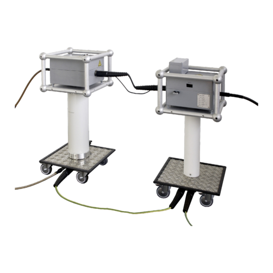
- Page 12 ICMflex Partial discharge and loss factor measurement system The following Figure 2 shows a 50 kV set consisting of a T-filter T50/1 (left) and the ICMflex model for 50 kV (right). Figure 2: 50 kV test set Based on application necessity, it is possible to order the ICMflex acquisition system in different configura- tions.
-
Page 13: Measurement Set-Up
ICMflex Partial discharge and loss factor measurement system Measurement set-up Verifying the part list Before starting the installation, it is recommended to check if all parts are available. The standard package consists of the following items: Acquisition unit ICMflex, HV filter (optional), Battery pack type BAT2A, Battery charger, Fibre optic cable (10 m);... -
Page 14: Location
ICMflex Partial discharge and loss factor measurement system Location As mentioned above in the general procedure prior to installation, please search for a safe location close the specimen to install the equipment. Ask for a scaffold, delineation, or covered area, if required, as shown in Figure 4, and prevent environmental conditions with high relative humidity and extreme temperatures. - Page 15 ICMflex Partial discharge and loss factor measurement system Figure 5: Filter connectors The coaxial output of the filter (left picture in Figure 6) serves for the analogue noise gating. A noise decou- pling circuit is directly built into the filter to capture any noise originating from the high voltage supply itself. A coaxial connection between filter output and ICMflex input (picture on the right-hand side of Figure 6) has to be established for the use of the gating option.
- Page 16 ICMflex Partial discharge and loss factor measurement system The most convenient way to communicate with the instrument is via Bluetooth interface. Here, no further cabling is needed. In case, a Bluetooth connection cannot be established, it is possible to use the fibre optic serial link instead.
-
Page 17: Software And Driver Installation
ICMflex Partial discharge and loss factor measurement system Software and driver installation The ICMflex comes with a Windows based software package on a USB stick or CD. The software can be in- stalled on every Windows operating system of 32-bit or 64-bit architecture (version 7, 8, and 10). If a computer is provided by Power Diagnostix, the software and the instrument drivers are pre-installed and readily config- ured. -
Page 18: Setting Up A Bluetooth Com Port
ICMflex Partial discharge and loss factor measurement system Setting up a Bluetooth COM port All Bluetooth devices on computer systems can provide so called virtual COM ports. These COM ports will be used to establish a connection with the ICMflex. Standard laptops come with built-in Bluetooth interfaces. If not, it is possible to use external USB-Bluetooth devices. -
Page 19: Setting Up A Fibre Optic Communication Port (Usb Serial Com)
ICMflex Partial discharge and loss factor measurement system Figure 16: Device manager If successful, the hardware manager of Windows will automatically install a virtual COM port for the new device. Typically, two COM ports will be installed for the ICMflex as shown in Figure 16. Enable both ports with the ICMflex software interface settings as described in section 5.2. - Page 20 ICMflex Partial discharge and loss factor measurement system If the computer does not recognise the cable, you need to install the drivers manually. Go to the device manager and select the related COM port. After a right mouse click you can select ‘Update driver’. A window comparable to Figure 18 will pop up.
-
Page 21: Icmflex Software
ICMflex Partial discharge and loss factor measurement system ICMflex software First steps The ICMflex software comes with default factory settings after start-up. All settings will be saved when closing the application. Settings affecting the acquisition circuit are sent to the ICMflex acquisition box when being changed. -
Page 22: Connecting To The Instrument
ICMflex Partial discharge and loss factor measurement system Connecting to the instrument Before connecting to the instrument, it is recommended to check the COM port settings in the menu ‘ Options-> Interface Settings’ as shown in Figure 21. Enable the port number as specified for Bluetooth or fibre optic communication (see section 4.2 and 4.3). -
Page 23: Firmware Updates And Configuration Files
ICMflex Partial discharge and loss factor measurement system Firmware updates and configuration files After a software upgrade, a pop-up window may appear indicating the availability of a new firmware version (see Figure 23). Do not hesitate to install the update as it includes important recent improvements for the unit. Figure 23: ... -
Page 24: Principle Of Operation
ICMflex Partial discharge and loss factor measurement system The device configuration panel shows detailed information about the instrument, e.g., the serial number and installed firmware version. To get full information connect to the instrument and open the device configuration panel again. A screenshot of the device configuration is shown in Figure 27. Since the instrument can be ordered in different configurations, check if all features are available as expected, e.g., Partial discharge measurement Partial discharge fault location for cables... - Page 25 ICMflex Partial discharge and loss factor measurement system Figure 28: PD display mode the current PD peak magnitude is shown in the upper left corner of this graph. The magnitude has to be cali- brated (see applications notes in section 5.7). The time domain graph in the lower left area can be used to evaluate single PD events and the reflections of pulses, as detected on medium and high voltage cable insula- tion systems on a time-based curve (resolution of 100 Msamples/second).
-
Page 26: Loc Display Mode
ICMflex Partial discharge and loss factor measurement system 5.4.2 LOC display mode The second display mode is called LOC mode and serves to perform PD fault location measurements on medium and high voltage cables. An ICMflex with option LOC for cable fault location comes with a digital storage oscilloscope (DSO) to process partial discharge signals on a time-based curve. - Page 27 ICMflex Partial discharge and loss factor measurement system The principle of the time domain reflectometry is illustrated in Figure 30. The travel paths of the first three reflec- tions of the original partial discharge pulse that enters the coupling unit of the ICMflex are displayed in three different colours.
-
Page 28: Rec Display Mode
ICMflex Partial discharge and loss factor measurement system 5.4.3 REC display mode The third display mode is called REC mode. It is used to plot results into a summarising table or graph. The collected data can be displayed vs. time or vs. voltage. The voltage graph in the upper left area remains un- changed. - Page 29 ICMflex Partial discharge and loss factor measurement system For using the manual mode, it is mandatory to start the measurement by pressing the button ‘Start Rec’. To accumulate readings, the button ‘Trigger’ can be used, when reaching a required voltage step. The relevant data, such as the applied voltage, tan delta, tan delta tip-up value, capacitance, and apparent charge levels, will be registered and represented in a graph versus voltage or time in the lower left chart.
-
Page 30: Display Mode Settings
ICMflex Partial discharge and loss factor measurement system Display mode settings Settings affecting the individual graphs or measurements can be found in the lower area of the window above the functional keys. Depending on the graph or area activated (indicated by a dark grey area in the back- ground, e. g. -
Page 31: Settings For Pd Fault Location
ICMflex Partial discharge and loss factor measurement system Lowpass 250 kHz, 600 kHz, Depends on the upper cut-off frequency of the PD bandpass 800 kHz filter. 0–100 % LLD stands for Low Level Discriminator. This is the minimum trigger level for PD pulse acquisition. A minimum level of 2 % should be set to eliminate small noise pulses. -
Page 32: Settings For The Record Mode
ICMflex Partial discharge and loss factor measurement system Trg. Mode Auto Auto: This mode displays continuously a signal on the Normal DSO graph (triggered or non-triggered signals). Single Shot Normal: This mode displays continuously triggered signals only. Single Shot: This mode displays a single triggered PD event and stops the refresh subsequently. - Page 33 ICMflex Partial discharge and loss factor measurement system Csx (see remark No limit; to be Capacitance value of the shunt capacitor of the test path. below) calculated before Please check the data sheet of your system or read the value high voltage is as written on the grey acquisition box.
-
Page 34: Functions And Menus
ICMflex Partial discharge and loss factor measurement system Functions and menus The ICMflex software offers multiple functions directly from the front panel or via the menu bar on top. These functions can vary, depending on the display mode chosen, or depending on the hardware options available with the instrument. - Page 35 ICMflex Partial discharge and loss factor measurement system The software can generate a standard report as ex- plained in section 5.6.2.1 and/or a detailed cable measurement report. The editable options for the de- tailed report are shown in a screenshot in Figure 39. In general, the represented measured data is com- parable.
- Page 36 ICMflex Partial discharge and loss factor measurement system 5.6.1.3 Connect A connection of the software to the ICMflex can be establish via the function key F6, by using the menu option as shown in Figure 41 or by pressing the ‘Search’ button in the key bar. Figure 41: ...
-
Page 37: Function Keys
ICMflex Partial discharge and loss factor measurement system 5.6.2 Function keys All main functions are shown on the bottom of the window (see figure below). Some buttons cover multiple functions depending on the display mode of the software. Figure 46: Function keys at the bottom of the application window 5.6.2.1 Report [F1] Pressing this button will open the pop-up window shown in Fig- ure 47. - Page 38 ICMflex Partial discharge and loss factor measurement system This function is available when being offline, means not connected to an instrument. It allows loading old measurements from hard disc or any other memory. Files saved with the ICMflex software come with the file suffix *.flx.
-
Page 39: Icmflex And Pd Calibration
ICMflex Partial discharge and loss factor measurement system ICMflex and PD calibration 5.7.1 Calibrators There is a broad range of impulse generators offered by Power Diagnostix for different purposes. The table below gives an overview of these calibrators. All of them allow the calibration of PD measurements according to IEC 60270/2000, except the CAL2B/C/D, since these calibrator models are not equipped with an injection capacitor to enable calibration on GIS. - Page 40 ICMflex Partial discharge and loss factor measurement system Power Diagnostix delivers its standard calibrators with a fully traceable DAkkS calibration (DK150680100). This calibration certificate documents the traceability according to national standards, which fulfil the units of measurement according to the International System of Units SI. The DAkkS (Deutsche Akkreditierungsstelle) is signatory to the multilateral agreement of the European co-operation for Accreditation (EA) for the mutual recognition of calibration certificates.
-
Page 41: Gating
ICMflex Partial discharge and loss factor measurement system Please ensure that the selected unit [pC/nC] and amplitude fit with the injected charge. For further information about calibration, please check sections 6.1.2and 6.2.2. z Always provide solid grounding of the instrument and the filter units Warning z Make sure that the cable/machine is de-energised before calibration. - Page 42 ICMflex Partial discharge and loss factor measurement system measured disturbance pulses. The gate level in percent is referring to the maximum scale of the PD pattern or PD scope view at the particular gain. In order to adjust the gate level to blind out the switching pulses of the VLF for instance, the general background noise must be investigated;...
-
Page 43: Application Notes
ICMflex Partial discharge and loss factor measurement system Application notes The application notes for medium and high voltage cables, rotating machines, and single stator bars de- scribe the specific measurement set-up, calibration, step by step procedure for performing the measurement, software usage, and evaluation criteria according to the relevant standards. - Page 44 ICMflex Partial discharge and loss factor measurement system Figure 56: CAL1B connected to MV cable (lab) Figure 57: CAL1B connected to MV cable (on-site) Common calibration levels for laboratory acceptance tests are in range of 2 to10 pC (CAL1A). However, for on-site testing the set-up sensitivity often does not allow such a sensitive calibration as in the laboratory. Due to this, calibrations are often made with injection levels from 100 pC to 2 nC (CAL1B).
- Page 45 ICMflex Partial discharge and loss factor measurement system Figure 58: Cable with shorted end Figure 59: Cable with open end The DSO screen in Figure 58 shows the first two reflections arriving at the measuring impendance. Since the cable has an open end, the time difference between the reference pulse and its first reflection represents twice the cable length.
-
Page 46: Standard Pd Measurement
ICMflex Partial discharge and loss factor measurement system 6.1.3 Standard PD measurement Once the calibration procedure is completed and the calibrator has been removed from the test specimen, the voltage may be switched on. Please pay attention to the correct settings of the shunt capacitor Csx (low or high) as mentioned in section 5.5.3. -
Page 47: Pd Measurements On Cables With High Capacitance
ICMflex Partial discharge and loss factor measurement system 6.1.4 PD measurements on cables with high capacitance For PD measurements on specimen with high capacitances Power Diagnostix provides the extension box CSX900 (Figure 63) which extends the Csx value of the ICMflex to 900 µF. The box is mounted onto an isolator of predefined height according to the maximum voltage level of the VLF source. -
Page 48: Pd Fault Location
ICMflex Partial discharge and loss factor measurement system 6.1.5 PD fault location When the PD pattern is mapped and saved and required notes are made; focus should be laid on the Digital Storage Oscilloscope (DSO). Here, each partial discharge pulse is represented on a time-based curve. First, the settings must be modified so that the reference pulse and the two first reflections arriving at the coupling unit are visible in the screen as explained in section 5.4.2. - Page 49 ICMflex Partial discharge and loss factor measurement system The main task of the replay function is the correct position- ing of the cursor for the reference pulse (grey cursor in Fig- ure 67) and the cursor for the first reflection arriving at the coupling capacitor (green cursor).
-
Page 50: Test Voltage Recommendations And Criteria
ICMflex Partial discharge and loss factor measurement system 6.1.6 Test voltage recommendations and criteria According to the relevant standards for medium and high voltage cable testing, test voltages, sequences, and PD evaluation criteria are described in relation to the cable’s voltage class. Please select the test type to be performed i.e., acceptance testing or on-site testing. - Page 51 ICMflex Partial discharge and loss factor measurement system Besides the IEC standards, there are applicable IEEE publications as well. The general procedures and crite- ria do not differ too much from the IEC. However, interesting in the IEEE standards are the test voltage criteria for testing at very low frequency (VLF).
-
Page 52: Typical Pd Patterns And Tan Delta Levels
ICMflex Partial discharge and loss factor measurement system 6.1.7 Typical PD patterns and tan delta levels MV class cables are tested in the factory according to common IEC standards. The acceptance level for new cable systems is < 2 pC or even less. Therefore, all PD detected on MV cables under applied voltage up to 1.5 x rated voltage should be considered as a problem within the cable or its accessories. -
Page 53: Normative References
ICMflex Partial discharge and loss factor measurement system The loss factor values measured on MV cables are usually specified according to the cable insulation system and voltage level U , 2 U or the tip-up between 2 U and U . -
Page 54: Rotating Machines
ICMflex Partial discharge and loss factor measurement system Rotating machines 6.2.1 Test set-up A general description of the measurement set-up is given in section 3. In this case, the focus is set on the rotating machines application. Of main importance is the interconnection between the main grounding of the high voltage power supply, i.e., a transformer or resonance test set, and the main grounding of the machine frame. -
Page 55: Pd Measurements
ICMflex Partial discharge and loss factor measurement system It is recommended to make a calibration using the PD attenuator as well. Due to the properties of the insu- lation materials and the winding manufacturing techniques of an epoxy mica insulation system, it is known that the related partial discharge pulses can produce strong amplitudes. - Page 56 ICMflex Partial discharge and loss factor measurement system The next step of the measurement process is identification of the partial discharge inception voltage (P ). Important for determining the P a sensitive and slow ramp-up of the test voltage. A typical test sequence used for partial discharge measurements is, for instance, the one for tan delta measuring, as exemplarily depicted in Fig- ure 72.
-
Page 57: Step-By-Step Guide
ICMflex Partial discharge and loss factor measurement system 6.2.4 Step-by-step guide In order to simplify the measurements, a step-by-step guide was implemented into the ICMflex standard soft- ware, which guides users through the required steps that must be fulfilled prior and during the measurement. To enable the step-by-step guide, the option must be activat- ed via ‘Edit->Edit Preferences’... - Page 58 ICMflex Partial discharge and loss factor measurement system After filling in the individual fields, the background colour of the relevant text box to be filled changes from red to black after confirming by pressing the enter button. The nominal voltage to be entered is the operating phase to phase voltage of the stator winding.
- Page 59 ICMflex Partial discharge and loss factor measurement system After entering and confirming the set time, the user is asked to enter the file name (Figure 77). He can do this by pushing the button ‘Filename’ in the bottom guidance menu. All measured data at each voltage interval will be stored under the entered file name into in the relevant folder on the computer’s hard drive.
- Page 60 ICMflex Partial discharge and loss factor measurement system Figure 78: PD calibration Each step that has to be performed to complete the calibration sequence as shown in Figure 79. Connect the calibrator Start pattern: wait for 10 s (standard acquisition time for calibration) Double click on the calibrator pulse Figure 79: ...
- Page 61 ICMflex Partial discharge and loss factor measurement system Step 4: Apply voltage The next step in the measurement process is to apply voltage. In the upper guidance bar, the required voltage level will be indicated (see Figure 80). It is represented as a phase to ground or phase to phase level. From this point in the sequence, the user can turn back to the forgoing step by pushing the button ‘<...
- Page 62 ICMflex Partial discharge and loss factor measurement system Figure 82: Guidance screen for starting the PD pattern Figure 83: Guidance screen after completing pattern ac- quisition The pattern acquisition will be started by pressing the ‘Start Pattern’ button at the bottom of the guidance screen (see Figure 82). The pattern will be collected according to the fixed set time. Once the pattern is ac- quired, the second guidance bar will indicate ‘Pattern Acquisition finished’...
- Page 63 ICMflex Partial discharge and loss factor measurement system In addition to the gain settings for both voltage dividers, the gain for the partial discharge measurement must also be monitored. After reaching a voltage step, please check if the present PD activity is within the maxi- mum scale of the pattern.
-
Page 64: Typical Pd Patterns And Tan Delta Levels On Rotating Machines
ICMflex Partial discharge and loss factor measurement system 6.2.5 Typical PD patterns and tan delta levels on rotating machines To simplify the evaluation of all measurement results you can find here some common partial discharge patterns versus PD origin and tan delta evaluation criteria as known from rotating machines standards and other related literature. - Page 65 ICMflex Partial discharge and loss factor measurement system PD PHENOMENA TYPICAL FURTHER PD PATTERN EXAMPLE RANGE ANALYSIS RECOMMENDED Thermally aged main insula- <5 nC >5 nC tion symmetrical in both half-cy- cles Slot discharges with machine 0 nC >5 nC bars non-symmetrical predominantly in the negative...
-
Page 66: Normative References
ICMflex Partial discharge and loss factor measurement system 6.2.6 Normative references TS IEC 600034-27: Off-line partial discharge measurements on the stator winding insulation of rotating electrical machines IEC 600034-27-3: Dielectric dissipation factor measurement on stator winding insulation of rotating elec- trical machines IEC 60894: Guide for test procedure for the measurement of loss tangent of coils and bars for ma- chine windings... -
Page 67: Test Set-Up
ICMflex Partial discharge and loss factor measurement system 6.3.2 Test set-up The PD and tan delta measurement setup using the standard ICMflex is very similar to testing of complete windings (see section 6.2.1). Instead of connecting the grounding to the motor or generators frame, it is connected to the simulated slot applied on the straight part. -
Page 68: Typical Patterns And Tan Delta Levels On Single Stator Bars
ICMflex Partial discharge and loss factor measurement system Figure 90: Tan delta measurement with guard rings 6.3.5 Typical patterns and tan delta levels on single stator bars The partial discharge patterns are very similar to the ones given for rotating machines in section 6.2.5. How- ever, for the tan delta measurement, different criteria are applicable. Common levels are specified in Table 9 mentioned below. -
Page 69: Options
ICMflex Partial discharge and loss factor measurement system Options Guard Ring Control (GRC) In order to meet with the requirements of the existing IEEE 286-2000 and the IEC 60034-27-3 standard for dielectric dissipation factor test- ing (also known as tan delta testing) on rotating machine stator bars, Power Diagnostix made a re-design of the existing ICMflex, i.e., the ICMflex GRC ‘Guard Ring Control’. - Page 70 ICMflex Partial discharge and loss factor measurement system With an additional PD input there are some more options selectable within the preferences panel of the ICMflex soft- ware. These are shown in Figure 93. The user can deter- mine if different filter configurations should be used for the main and the auxiliary channel (not recommended) and if these two channels should use the same configuration or not.
- Page 71 ICMflex Partial discharge and loss factor measurement system polarities at the end of the dead time (‘Peak Pol.’). Additionally, the ICMflex2 offers an AND combination of both methods (‘F&P Pol.’). The effectiveness of these methods is depending on the repetition rate and the amplitude ratio of the two pulse sources.
- Page 72 ICMflex Partial discharge and loss factor measurement system Figure 94: General connection diagram for ICMflex2 User guide for ICMflex pdix.com...
- Page 73 ICMflex Partial discharge and loss factor measurement system Figure 95: ICMflex2 and line filter LF450 installed on an external coupling capacitor pdix.com User guide for ICMflex...
- Page 74 ICMflex Partial discharge and loss factor measurement system Polarity of first pulse exceeding the LLD Sampled peak values Polarity of maximum pulse amplitude Peak hold Pulse from test object Pulse from test voltage source Figure 97: positive polarity on channel 1, nega- Figure 96: and have positive polarity on both channels tive polarity on channel 2;...
-
Page 75: Gating Via Fibre Optic Link (Fo Gating)
ICMflex Partial discharge and loss factor measurement system Gating via fibre optic link (FO gating) An ICMflex with an FO gating function comes with an additional terminal (‘FO GATE IN’) for a Fibre Optic (FO) cable, which transmits a signal to HV potential provided by a gating signal transmitter (GST1). The transmitter is included in the scope of delivery if FO gating is ordered. - Page 76 ICMflex Partial discharge and loss factor measurement system Figure 100: Gating connection diagram User guide for ICMflex pdix.com...
- Page 77 ICMflex Partial discharge and loss factor measurement system The gating signal transmitter GST1 is depicted in Figure 101. It offers a logarithmic amplification and can be set to three different frequency ranges (40–800 kHz, 2–20 MHz, or 200–600 MHz), which can be selected with a push button.
-
Page 78: Bypass
ICMflex Partial discharge and loss factor measurement system Bypass If the test object’s capacitance is too high, an ICMflex for tan delta measurements can be fitted with a C bypass to avoid overstressing of the shunt capacitor. With an active bypass, loss factor measurements are disabled but PD diagnostic is still possible. -
Page 79: Miscellaneous
ICMflex Partial discharge and loss factor measurement system Miscellaneous Maintenance The ICMflex does not require any maintenance on a regular basis. There is no fine adjustment on a regular basis required, as the partial discharge measurement is a relative measurement that is calibrated with a refer- ence source (charge calibrator, CAL series) prior to a measurement. -
Page 80: Declaration Of Conformity
ICMflex Partial discharge and loss factor measurement system Declaration of Conformity The manufacturer Power Diagnostix Instruments GmbH Vaalser Strasse 250 52074 Aachen Germany declares that the product ICMflex Partial discharge detector for use in high voltage areas provided it is installed, maintained, and used for which it was made, in accordance with relevant installation standards and manufacturer’s instruction, meets the requirements of the following directive(s): Low Voltage Directive 2014/35/EU EMC Directive 2004/108/EG... -
Page 81: Declaration Of Conformity
ICMflex Partial discharge and loss factor measurement system UK Declaration of Conformity The manufacturer Power Diagnostix Instruments GmbH Vaalser Strasse 250 52074 Aachen Germany declares that the product ICMflex Partial discharge detector for use in high voltage areas provided it is installed, maintained, and used for which it was made, in accordance with relevant installation standards and manufacturer’s instruction, meets the requirements of the following Statutory Instruments: SI 2016 no. 1101 The Electrical Equipment (Safety) Regulations 2016 SI 2016 no. -
Page 82: Technical Data (Standard Version)
ICMflex Partial discharge and loss factor measurement system Technical data (standard version) Mains supply: Battery operated (up to 6 hours) Power requirements: Approx. 20 VA Operation: Remote controlled via ICMflex software PD input impedance: 1 kΩ // 50 pF PD input sensitivity: <... -
Page 83: Weight And Dimensions
ICMflex Partial discharge and loss factor measurement system Weight and Dimensions TYPE RATED MAX. HEIGHT WIDTH LENGTH COMMENT VOLTAGE WEIGHT (RMS) Measurement system ICMflex 30 kV ICMflex 50 kV ICMflex 100 kV ICMflex 150 kV 1600 ICMflex >200 kV To be installed on separate HV reference capacitor of min. -
Page 84: Appendix
ICMflex Partial discharge and loss factor measurement system Appendix 10.1 What is the loss factor (or dissipation factor) tan delta? Building high voltage equipment requires using insulation material. Commonly used insulation materials show losses due to resistive currents or polarisation currents of dipoles. Often, the magnitude of these losses can be used as an indicator for the quality of the insulation. -
Page 85: Troubleshooting
ICMflex Partial discharge and loss factor measurement system 10.2 Troubleshooting The personal computer cannot find the ICMflex If no communication between the ICMflex and the software can be established, please reboot the control computer and check: if all necessary drivers are installed properly (see sections 4.2 and 4.3) if the battery is charged. - Page 86 ICMflex Partial discharge and loss factor measurement system The ICMflex application window appears very small on high resolution monitors in Windows 10. On PCs running Windows 10 with the Creator’s Update of 2017 the ICMflex application window may appear very small on high resolution monitors.
-
Page 87: National Instruments Hardening Guide
ICMflex Partial discharge and loss factor measurement system 10.3 National Instruments hardening guide 10.3.1 Introduction This manual will guide you through the Power Diagnostix proposed cyber security operation system hard- ening after the installation of a National Instruments based software product. The configuration refers to the Power Diagnostix software products, only. -
Page 88: Service Description
ICMflex Partial discharge and loss factor measurement system 10.3.3 Service description http://www.ni.com/product-documentation/14487/en/ User guide for ICMflex pdix.com... -
Page 89: Index
ICMflex Partial discharge and loss factor measurement system Index Loss factor measurement ........1, 3, 12 Low level discriminator ....31, 42, 46, 55, 70, 74 Acquisition box .............. 10 Analogue gating ......41, 42, 46, 55, 75, 77 Maintenance ..............79 Multi-contact connector ........ - Page 90 ICMflex Partial discharge and loss factor measurement system LANGUAGE | EN USER GUIDE Power Diagnostix Systems GmbH ∙ Vaalser Strasse 250 ∙ 52074 Aachen∙ Germany ∙Telephone +49 241 74927 ∙ Fax +49 241 79521 ∙ www.pdix.com ICMflex_UG_EN_1.00 July 2023 © Power Diagnostix Systems GmbH 2023...
Need help?
Do you have a question about the Power Diagnostix ICMflex and is the answer not in the manual?
Questions and answers