Table of Contents
Advertisement
Advertisement
Table of Contents

Related Manuals for Megger DLRO


Summary of Contents for Megger DLRO
- Page 1 ® Advanced Test Equipment Rentals www.atecorp.com 800-404-ATEC (2832) AVTM24-1J Rev A April 2006 Instruction Manual ® DLRO Digital Low Resistance Ohmmeters Catalog No. 247000 Series Valley Forge Corporate Center 2621 Van Buren Avenue Norristown, PA 19403-2329 U.S.A. 610-676-8500 www.megger.com...
- Page 3 ® DLRO Digital Low Resistance Ohmmeters Catalog No. 247000 Series...
- Page 4 If the product or its individual instruments are used for purposes other than those specified herein, confirmation of their validity and suitability must be obtained from Megger. Refer to the warranty information below. Specifications are subject to change without notice.
-
Page 5: Table Of Contents
Table of Contents 1.0 10 Ampere Systems ..................1 Section A INTRODUCTION ............1 Section B SAFETY PRECAUTIONS ..........3 Section C RECEIVING INSTRUCTIONS ........5 Section D SPECIFICATIONS............7 Section E CIRCUIT DESCRIPTION ...........15 Section F CONTROLS AND CONNECTIONS .....19 Section G OPERATING PROCEDURE........23 Section H APPLICATIONS .............27 Section I MAINTENANCE .............31 Section J FIELD REPLACEABLE PARTS LIST.....33... -
Page 6: List Of Figures
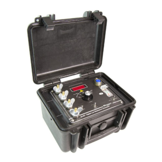
List of Figures Figure 1: Cat. No. 247000 DLRO instrument without charger ... iii Figure 2: Various DLRO Unit Combinations........6 Figure 3: Controls & Connections............21 Figure 4: Typical Connections to a Test Sample......25 Figure 5: Cat. No. 247101 DLRO consists of three elements: Left: 100A Current Source Center: Measuring Module Right: Charger Module for Measuring Module........36... - Page 7 Figure 1: Catalog No. 247000 DLRO instrument without charger AVTM24-1J Rev A April 2006...
- Page 8 AVTM24-1J Rev A April 2006...
-
Page 9: 10 Ampere Systems
10 Ampere Systems Section A INTRODUCTION Part 1.0 of this manual applies to a series of instruments; the principal models are Catalog Numbers 247000, 247001, 247002. Part 2.0 describes the 100 Ampere systems including catalog numbers 247100, 247101 and 247120. The Catalog No. - Page 10 The Catalog No. 247100 is a 100 Ampere Test System composed of a Catalog No. 247000 Measuring Module, and a Cat. No. 247120 100-amp power supply. The Catalog No. 24701 is also a 100 ampere test system. The ohmmeter has four terminals for a Kelvin connection to the sample under test, and it is recommended that Biddle test leads shown in Bulletin 24-1 be used with this instrument.
-
Page 11: Section B Safety Precautions
Section B SAFETY PRECAUTIONS SAFETY IS THE RESPONSIBILITY OF THE USER La seguridad es la responsabilidad del operador WARNING Do NOT connect this instrument to energized circuits. The Digital Low Resistance Ohmmeters have been designed and constructed to meet the requirements of ANSI/ISDA S82.01-1994. - Page 12 AVTM24-1J REV A April 2006...
-
Page 13: Section C Receiving Instructions
Megger, Norristown, PA 19403 of any shortage of materials. The instrument should be examined for damage received in transit. If any damage is found, file a claim with the carrier at once and notify Megger or its nearest representative giving a detailed description of the damages observed. -
Page 14: Figure 2: Various Dlro Unit Combinations
Catalog No. 247000 with Charger Catalog No. 247001 Catalog No. 247101with Charger Figure 2: Various DLRO Unit Combinations AVTM24-1J REV A April 2006... -
Page 15: Section D Specifications
Section D SPECIFICATIONS Ranges, Resolution, Accuracy & Test Current TEST CURRENT LIMIT OF ERROR RANGE RESOLUTION AMPERES 1 year 1 year (±20%) 15-35°C 0-50°C 0.000 -5.999 mO 1 µO ¼ % Rdg + 1 lsd* ½ % Rdg + 1lsd* 00.00 -59.99 mO 10 µO ¼... - Page 16 Interference Error in item under test caused by Effects: line- frequency current of 0.1X test current: ±l lsd Error caused by 5-gauss line- frequency magnetic field: ±2 lsd Error caused by connection to ground or voltage to ground (assuming battery operation): None Input One volt peak may be applied Protection:...
- Page 17 Specifications Calibration Internal zero and span adjustments Adjustments: for all ranges. Test Lead Potential Leads (P1. P2): Resistance No limitations. Requirements: Current Leads (C1, C2): each lead 20 milliohms nominal. Deviations affect test current but do not affect accuracy unless they are large compared to the measuring range.
- Page 18 Battery Separate charger unit plugs into Charger: receptacle on measuring unit. Full charge in 14 hours. Charging may be continued while instrument is operating. Fused, with UL listed 3- wire line cord and plug. Power requirements, 0.22 amps at 115 volts, 50/60 Hz;...
- Page 19 Specifications Safety: Meets all applicable requirements of ANSI/ISA S82.01-1994. Highest voltage existing (except in charger primary and line supply primary) is 6 volts. Case: The measuring unit and charger have rugged molded case with handles and removable hinged lids. The measuring unit lid can be used as a sun shield.
- Page 20 Catalog Numbers and Unit Combinations for 10-Ampere Systems CATALOG DESCRIPTION 247000 Instrument with Internal Rechargeable Batteries and separate 115V 50/60 Hz Charger Unit. Range: 0 to 60 Ohms in 5 ranges, 0 to 5.999 Milliohms lowest range (Note 1). 247000-3 Same as Cat.
- Page 21 Specifications Catalog Numbers and Unit Combinations for 10-Ampere Systems CATALOG DESCRIPTION 247100 See Part 2.0 247101 See Part 2.0 247120 See Part 2.0 NOTES: Note 1: Leads not included. (See Bulletin 24-1 for recommended test leads.) See Page 36 for information concerning 100-Ampere systems.
- Page 22 AVTM24-1J REV A April 2006...
-
Page 23: Section E Circuit Description
Section E CIRCUIT DESCRIPTION Ra and RA’ set the test current to the values listed in Section range. On the Specifications; there is a pair of these resistors for each 6 mΩ 10A range, test current is also affected by the resistance of the test leads connected to the C1and C2 terminals. - Page 24 The display would be: Ω × 0015 × Ω If the test current is reduced to 9 amperes: Ω × 0015 × Ω Thus the reading is independent of test current variations caused by changes in battery voltage, or by different test lead resistance.
- Page 25 Circuit Descriptions batteries, even if they are allowed to remain on charge indefinitely. Charging currents are set at the factory and need readjustment only when batteries are replaced. Zener diodes protect the instrument from damage caused by switching transients that may occur when measuring the resistance of inductive samples, and by 60 Hz pickup that may occur when measuring large equipment in high voltage switchyards.
- Page 26 AVTM24-1J REV A April 2006...
-
Page 27: Section F Controls And Connections
Section F CONTROLS AND CONNECTIONS Fig. 3 shows a front panel view of Catalog No. 247000 with functional parts and operating controls labeled. S4, M1 Battery test meter M1 shows the relative state of charge of the internal rechargeable batteries. With S4 in the “Display”... - Page 28 C1, P1, P2, C2 Four terminals with wing—nuts are provided for making a Kelvin connection to the specimen under test. Test current is available at the C1 and C2 terminals, and the actual resistance is measured between the points where leads connected to the P1 and P2 terminals are placed.
-
Page 29: Figure 3: Controls & Connections
Controls & Connections Figure 3: Controls & Connections AVTM24-1J REV A April 2006... - Page 30 AVTM24-1J REV A April 2006...
-
Page 31: Section G Operating Procedure
Section G OPERATING PROCEDURE RECHARGEABLE BATTERY MODELS § Battery Check Before using the instrument, check the display and measuring circuit batteries. The battery test meter will indicate their relative state of charge. The battery test is valid only when the instrument is operating on the range that it is intended to be used, connected to a test specimen or with the C1 and C2 leads shorted. - Page 32 § Very Low Resistance For full accuracy when reading below 0.1 mO, use the average of forward and reverse readings. Make the reverse reading by holding the “forward-reverse” switch in the “reverse” position. A minus sign will appear in the (—) display when this switch is in the reverse position;...
-
Page 33: Figure 4: Typical Connections To A Test Sample
Operating Procedure 3. Using Kelvin Clip leads. Figure 4: Typical Connections to a Test Sample. 4. Charging Batteries To charge the batteries, remove the jumper plug from and connect the output lead of the battery charger to J2. A pilot light on the charger will indicate when it is connected to an energized ac power line. - Page 34 AVTM24-1J REV A April 2006...
-
Page 35: Section H Applications
On/ Off switch. It is not recommended to use a DLRO for measuring transformers and other large inductive devices. The transformer ohmmeter is specifically designed for inductive devices. -
Page 36: Other Applications
For personnel safety and to protect the DLRO instrument, proceed as follows: 1. Firmly connect C1and C2 leads before switching the DLRO on. 2. Switch the DLRO off before disconnecting Cl or C2 connections. MEASURING WINDING RESISTANCE OF ELECTRIC MOTORS Fig.3B shows hand spikes being used to make contact with... - Page 37 Applications INTERFERENCE Alternating current interference in the sample under test can cause several digits fluctuation in a displayed reading. Interference can also be due to pickup in long test leads, especially in the vicinity of strong electric or magnetic fields. In these cases, fluctuation of the reading can sometimes be reduced by twisting the pairs of leads together.
- Page 38 When making a measurement of a totally new kind, interchange the C leads to determine whether there is any DC interference. AVTM24-1J REV A April 2006...
-
Page 39: Section I Maintenance
Section I MAINTENANCE Remove the instrument from its case by removing the screws at each corner of the panel. RECHARGEABLE BATTERIES The internal rechargeable batteries may fail to hold a charge after several hundred charge-discharge cycles, resulting in shorter than normal service life. In addition to a low reading on the battery test meter, battery failure evidence is also given by a dim display and/or readings that appear unstable or fluctuate more than normal. - Page 40 After batteries are replaced, charging currents must be checked and, if necessary, readjusted to accommodate the characteristics of the new cells. Contact Megger for instructions. AVTM24-1J REV A April 2006...
-
Page 41: Section J Field Replaceable Parts List
Section J FIELD REPLACEABLE PARTS LIST CAT. NOS. 247000, 247000-47 PART NO. QTY. DESCRIPTION See Table Battery Charger, complete 5026 Wing Nut 4690-5 Knob 15568-2 B2,B3 1.25V, Size F, 7 A.H. Nickel-Cadmium rechargeable battery (Gould 7.0 SCB or equivalent) 15568-1 1.25V Size D, 4 A.H. - Page 42 Catalog Nos. 247001, 247002 Part No. Qty. DESCRIPTION 5026 Wing Nut 25774 Knob (247001) 15568-2 B2, B3 1.25V, size F, 7 A.H. Nickel-Cadmium rechargeable battery (Gould 7.0 SCB or equivalent) 15568-1 1.25V, size F, 4 A.H. Nickel-Cadmium rechargeable battery (Gould 4.0 SCB or equivalent) 15676 Battery Retainer Strap See Table...
-
Page 43: Section K Warranty & Repair
Section K WARRANTY & REPAIR WARRANTY: All products supplied by Megger are warranted against all defects in material and workmanship for a period of one year following shipment. Our liability is specifically limited to replacing or repairing, at our option, defective equipment. -
Page 44: Figure 5: Cat. No. 247101 Dlro Consists Of Three Elements
Prepaid and Insured and marked for the attention. of the Instrument Service manager. Figure 5: Cat. No. 247101 DLRO consists of three elements: Left: 100A Current Source Center: Measuring Module Right: Charger Module for Measuring Module AVTM24-1J REV A April 2006... -
Page 45: 100 Ampere System
100 Ampere System Section A INTRODUCTION The Catalog No. 247100 DLRO instrument is a digital low resistance ohmmeter designed specifically to measure very low resistance (zero to 600 micro-ohms) with a test current of 100 amperes. This capability is required by some standard methods of testing large switchgear. - Page 46 100A and the rated normal current”. This 100-ampere test capability is achieved by adding a special current source and range module to a more general- purpose instrument, the Catalog No. 247000 DLRO, while retaining all the features of that instrument. AVTM24-1J REV A April 2006...
- Page 47 Introduction This part of the manual covers only the 100-Ampere portion of the system. Refer to Part I for complete instructions for the basic Cat. No. 247000 instrument. AVTM24-1J REV A April 2006...
- Page 48 AVTM24-1J REV A April 2006...
-
Page 49: Section B Safety
Section B SAFETY SAFETY IS THE RESPONSIBILITY OF THE USER La seguridad es la responsabilidad del operador WARNING Do NOT connect this instrument to energized circuits. The line-operated 100-Ampere current source should be used and maintained by trained personnel who are familiar with the usual precautions for handling portable line- operated equipment. - Page 50 AVTM24-1J REV A April 2006...
-
Page 51: Section C Description & Specifications
Section C DESCRIPTION & SPECIFICATIONS DESCRIPTION The components of the measuring system are as follows: 1. Compact DLRO measuring module with rechargeable battery in molded case. 2. Battery Charger in similar molded case. 3. 100-Ampere DC current source having four test connection terminals used for the 100-Amp range. - Page 52 247100 Complete 100 Amp. system for 115V operation; includes 247000-3, 247120. 247100-47 Complete 100 Amp. system for 230V operation; includes 247000-3-47, 247120-47. 247101 Complete 100 Amp system for 115 V operation; includes 247001-3 & 247120 247101-47 Complete 100 Amp system for 230 V operation;...
- Page 53 Description & Specifications Specifications Measurement Data TEST LIMIT OF ERROR CURRENT RANGE RESOLUTION 1 year 1 year AMPERES 15-35°C 0-50°C 000.0 - 600.0 mO 0.1 µO ½ % Rdg + 2 lsd* 1 % Rdg + 2 lsd* *(Least Significant Digit) Response (After ON—OFF switch is closed): Time:...
- Page 54 Dimensions: 13 ½” wide x 9 ½” deep x 7 1/2” high (34.2 x 29.1 x 19 cm) Test Lead Requirements: Potential No limitations. Leads (P1, P2): Current Leads 6.7 milliohms each. (C1, C2): Deviations will not affect accuracy, but resistance changes may result in less than 100A test current.
-
Page 55: Section D Operating Procedure
Section D OPERATING PROCEDURE FOLLOW THE SAFETY PRECAUTIONS OF SECTION B MEASUREMENTS ON 600µO (100-Ampere) DLRO Range 1. Connections and Turn-On Connect the test sample to the terminals as shown in Figure 13. Make sure the current connections are clean and tight. - Page 56 2. Test Current Adjustment Test current indicated on the ammeter should be 100A. If adjustment is necessary, it can be made by the current adjustment knob. Fluctuations in test current may be caused by line voltage swings or poor connections. 3.
-
Page 57: Figure 6: Arrangement For Making Measurements In The 100- Ampere Range
Operating Procedure Figure 6: Arrangement for Making Measurements in the 100- Ampere Range The maximum duty cycle for rated accuracy is: At 50°C ambient: continuous. 4. Display The display reads directly in micro-ohms regardless of the range switch setting on the instrument. AVTM24-1J REV A April 2006... - Page 58 MEASUREMENTS ON HIGHER RESISTANCE RANGES To use the instrument on its other ranges, replace the small jumper plug in the panel. Operation is now as described for Cat. No. 247000 in Part 1. AVTM24-1J REV A April 2006...
-
Page 59: Section E Maintenance
Section E MAINTENANCE Before calibrating the 600 micro-ohm range, be sure that the measuring module is calibrated as shown in Part I. Connect the test leads to a resistance standard of about 100 micro-ohms which will tolerate 100 Amperes. A “Reichsanstalt”... - Page 60 AVTM24-1J REV A April 2006...
-
Page 61: Section G Recommended Test Leads
Section G RECOMMENDED TEST LEADS Megger test leads recommended for use with the 100- ampere range are as follows: Potential Leads, Pair, with Single Hand Spikes: Cat. No. 242021-7 5 ft. #14 AWG. Cat. No. 242021-18 20 ft. #10 AWG. - Page 62 AVTM24-1J REV A April 2006...
-
Page 63: Section H Warranty And Repair
Section H WARRANTY and REPAIR WARRANTY All products supplied by Megger are warranted against all defects in material and workmanship for a period of one year following shipment. Our liability is specifically limited to replacing or repairing, at our option, defective equipment. - Page 64 Prepaid and Insured and marked for the attention of the Instrument Service Manager. AVTM24-1J REV A April 2006...
-
Page 65: Section J Field Replaceable Parts List
Section J FIELD REPLACEABLE PARTS LIST PART NO. DESCRIPTION 4127-1 Input Cable AVTM24-1J REV A April 2006... - Page 66 AVTM24-1J REV A April 2006...
-
Page 67: -11 Option Input Protection
-11 OPTION INPUT PROTECTION The revised circuit does not degrade calibration or performance. The customer must use the same rating fuses as provided on original installation (one set of spare fuses supplied with instrument. The safety precaution “Do Not Connect This Instrument To Energized Circuits” remains in effect. -
Page 68: Avtm24-1J Rev A April
AVTM24-1J REV A April 2006...
Need help?
Do you have a question about the DLRO and is the answer not in the manual?
Questions and answers