Table of Contents
Advertisement
Quick Links
Advertisement
Table of Contents

Related Manuals for Megger Ducter DLRO2X


Summary of Contents for Megger Ducter DLRO2X
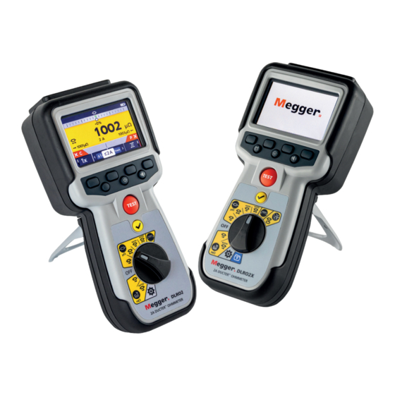
- Page 1 DLRO2 and DLRO2X Ducter™ Low Resistance Ohmmeter 2 A User Guide...
- Page 2 T +44 (0)1304 502101 F +44 (0)1304 207342 www.megger.com Megger Ltd reserves the right to alter the specification of its products from time to time without notice. Although every effort is made to ensure the accuracy of the information contained within this document it is not warranted or represented by Megger Ltd.
- Page 3 Directive 2014/53/EU. Other equipment manufactured by Megger Instruments Limited described in this user guide is in compliance with Directives 2014/30/EU and 2014/35/EU where they apply. The full text of Megger Instruments EU declarations of conformity are available at the following internet address: megger.com/eu-dofc www.megger.com...
-
Page 4: Table Of Contents
4.2.6. Test limit warnings (DLRO2X) ......................... 21 5. Data Storage (DLRO2X only) ......................22 5.1. Create folder for test results ........................22 5.2. Save test results ............................23 5.3. Auto Save test results ..........................24 5.4. Review Asset results ..........................25 DLRO2 and DLRO2X www.megger.com... - Page 5 11. Settings ............................40 11.1. General settings ............................. 40 11.2. Pass Colour settings (DLRO2X) ......................41 11.3. Date and Time settings (DLRO2X) ......................42 11.4. Language settings ..........................42 11.5. Instrument Information ........................43 11.6. Firmware update ........................... 43 www.megger.com DLRO2 and DLRO2X...
- Page 6 14.1. Included Accessories ..........................50 14.2. Optional Accessories..........................50 14.3. Download PowerDB ..........................51 15. Calibration, Repair and Warranty ....................52 15.1. Return procedure ..........................52 16. Decommissioning ........................53 16.1. WEEE Directive ............................53 16.2. Battery disposal ............................. 53 DLRO2 and DLRO2X www.megger.com...
-
Page 7: Introduction
Introduction 1. Introduction This user guide details the operational and functional details of the Megger DLRO2 and DLRO2X Ducter Low Resistance Ohmmeter 2 A. Please read this user guide fully before attempting to use the DLRO2 units. Product Description The DLRO2 range are tough and truly hand held 2 A low resistance ohmmeters, designed to provide fast, accurate and repeatable measurements even in electrically noisy environments. -
Page 8: Applications
PDU boards, lightning protection systems, final circuits. DLRO2 and DLRO2X www.megger.com... -
Page 9: Company Web Site
Introduction Company web site Occasionally an information bulletin may be issued via the Megger web site. This may concern new accessories, new usage instructions or a software update. Please occasionally check on the Megger web site for anything applicable to your Megger instruments. -
Page 10: Safety Warnings
The voltage indicator and current discharge features must be regarded as additional safety features and MUST not substitute the normal safe working practice which MUST be followed. The instrument must not be used if any part of it is damaged or if the terminal shutter is missing. „ DLRO2 and DLRO2X www.megger.com... -
Page 11: Test Lead Safety Warnings
„ must not be touched during testing. Only Megger approved test leads with right-angled instrument connectors must be used with this instrument. „ Test leads must be at least 1 m in length and provide a total loop impedance ≥ 26 mΩ. -
Page 12: Safety, Hazard And Warning Symbols On The Instrument
NOTE: The warning will not operate if the instrument is set to OFF. Internal Error Warning. To clear the error, switch the instrument Internal Error Warning OFF and then back ON. Contact Megger if this does not clear the error. Refer to the user guide if this message shows. -
Page 13: Instrument Controls
Refer to 3.5 Leads, power and USB connections on page 16 Display Battery cover Soft keys (multifunction) Stand Test Limits On or Off (DLRO2X) Back-light control Save results / Auto Save On (DLRO2X) Test TICK button Rotary selection switch www.megger.com DLRO2 and DLRO2X... -
Page 14: Instrument Rotary Control Dlro2
Settings mode (grey) Off position Instrument Rotary Controls DLRO2X Item Description Item Description Rotary switch positions Inductive mode Settings mode (grey) Normal resistance mode Noise rejection mode Off position Data storage mode (blue) Long leads mode DLRO2 and DLRO2X www.megger.com... -
Page 15: Instrument Display
Unidirectional or bidirectional selection Noise indicator Inductive charge warning Units of measure (for latest result) Time (DLRO2X only) Reverse measurement result Auto Save activated (DLRO2X only) Selected test current Test Limits warning indicator (DLRO2X only) P continuity indicator www.megger.com DLRO2 and DLRO2X... -
Page 16: Leads, Power And Usb Connections
Item Description Rear attachment point for strap Slider in rear position Slider in front position Battery charger connection Connections: C1, P1, P2, C2 USB port (firmware updates or Data transfer (DLRO2X only) via USB stick) Front DLRO2 and DLRO2X www.megger.com... -
Page 17: The Difference Meter
This explanation of the Difference Meter is written in reference to resistance mode but the explanation applies equally to inductive mode. Resistance measurement is selected. The Difference Meter is inactive. Continuity is indicated for C and P leads www.megger.com DLRO2 and DLRO2X... - Page 18 Fifth measurement is made, the Difference Meter shows it’s result, relative to the reference measurement. This reading is now just -1% lower than the reference measurement. NOTE : NThe units remained unchanged as µΩ and are shown in black. DLRO2 and DLRO2X www.megger.com...
-
Page 19: Setting Up The Dlro2
WARNING : Charge NiMH cells only between 0 ºC and 40 ºC ambient temperature. 4.2.4 Setting Date and Time (DLRO2X) To set the Date and Time please Refer to 11.3 Date and Time settings (DLRO2X) on page 42 www.megger.com DLRO2 and DLRO2X... -
Page 20: Setting Test Limits (Dlro2X)
3. When the selection is complete use soft key 4 to click the TICK ( ) and to save your test limit settings. 4. Go back to the main Settings menu and do the same for the Upper Test Limit. DLRO2 and DLRO2X www.megger.com... -
Page 21: Test Limit Warnings (Dlro2X)
3. Visual and audible warning When the visual warning is activated an eye symbol will appear at the top of the display. When the visual and audible warning is activated this symbol will appear at the top of the display. www.megger.com DLRO2 and DLRO2X... -
Page 22: Data Storage (Dlro2X Only)
The Asset with the SAVE icon next to it will be used for saving results. (Refer to 5.3 Auto Save test results on page 24) 5. To view the results, click the TICK button ( DLRO2 and DLRO2X www.megger.com... -
Page 23: Save Test Results
2. On the Data storage page use the soft keys to select the Asset ID that you require the results to be added to and click the TICK button ( 3. You will then see confirmation that the results have been saved. www.megger.com DLRO2 and DLRO2X... -
Page 24: Auto Save Test Results
Asset ID name. 5. To view the results, turn the rotary switch to Data Storage mode, select the Asset ID and click the TICK button ( until the desired results are on screen. DLRO2 and DLRO2X www.megger.com... -
Page 25: Review Asset Results
4. Choose the time that the test was taken. 5. The results for that test on the chosen date will appear on screen. Use the soft keys to navigate up and down or delete the results. www.megger.com DLRO2 and DLRO2X... -
Page 26: Tests: Inductive Mode
C and P indicators show red background with for no continuity or green background with for good continuity. Proceed when both show . The continuity indicators are active during the test and will update if continuity changes. DLRO2 and DLRO2X www.megger.com... -
Page 27: Second Test
Do not remove the test leads until discharge is complete and the warning disappears. NOTE : If continuity is lost from either the C or P connection during a test, this screen will be displayed for 3 seconds. The DLRO2 will then return to the start of the test. www.megger.com DLRO2 and DLRO2X... -
Page 28: Auto Stop
TEST button. The Difference Meter is active. When the test is stopped the displayed result is static. DLRO2 and DLRO2X www.megger.com... -
Page 29: Second Test
) will flash on the left of the screen and an audible warning buzzer will sound. Do not remove the test leads until discharge is complete and the warning disappears. NOTE : The TICK button ( ) will set a new reference value. www.megger.com DLRO2 and DLRO2X... -
Page 30: Tests, Resistance Mode
When continuity is detected on both circuits, the C and P indicators will both be greyed out and the test will start automatically. If required, to stop the test press the TEST button. DLRO2 and DLRO2X www.megger.com... -
Page 31: Post Auto-Start, Unidirectional Test
P lead must be disconnected and reconnected to restart the test. Alternatively press the TEST button to start another test. Continuity on C or P has been lost. Re-establish continuity to start a new test. www.megger.com DLRO2 and DLRO2X... -
Page 32: Manual, Bidirectional / Unidirectional Resistance Mode
C and P indicators show red background with for no continuity or green background with for good continuity. Proceed when both show 4. To start the test press the TEST button. If required, to stop the test press the TEST button. DLRO2 and DLRO2X www.megger.com... -
Page 33: For A Unidirectional Test
‘Two previous results’ in the secondary screen, left is previous result and right is the result before that. To stop the test press the TEST button. If continuity is maintained, pressing the TEST button will start a new test www.megger.com DLRO2 and DLRO2X... -
Page 34: Tests, Long Leads Mode
Manual Start’ or ‘Long Leads Mode - Auto Start’ will show in the secondary field for a short time, the text then disappears to reveal the previous results fields. 2. Connect C1-C2 and P1-P2 to the instrument and the unit under test. DLRO2 and DLRO2X www.megger.com... -
Page 35: For Manual Mode
If both C and P continuity is made before the test mode is selected, the continuity flags will be shown in grey – this means that the user must disconnect and reconnect or press the TEST button to start the test. www.megger.com DLRO2 and DLRO2X... - Page 36 If the test has been stopped by the TEST button the continuity indicators will be grey. If continuity already is shown on the C and P connectors press the TEST button to re-start the test. DLRO2 and DLRO2X www.megger.com...
-
Page 37: Noise Rejection Mode (Dlro2X Only)
„ Restricted to single tests. „ In high noise mode, all soft keys are inactive. Megger DLR02 icons The test is pre-set to single measurement, 1 A with previous 2 results displayed. „ Confidence Meter™ 1. If it is not possible to obtain a stable, accurate... - Page 38 50% for example. In this situation the user may be happy with the stable value and choose to stop the test by pressing the TEST button. This is usually because the Confidence Meter™ is trying to resolve the measurement to a higher resolution than is currently displayed. DLRO2 and DLRO2X www.megger.com...
-
Page 39: Error And Warning Conditions
The fuses in DLRO2 are not user replaceable. If there is no continuity between the C terminals this will indicate that the internal fuse has been blown. The unit must be returned to Megger to be repaired. Refer to 15. Calibration, Repair and Warranty on page 52. www.megger.com... -
Page 40: Settings
Settings 11. Settings Megger DLR02 icons In this section various user settings can be adjusted or accessed. 11.1 General settings Switch the rotary switch to the settings mode (Refer to 9.1 General settings on page 28). µ µ Go to the general settings tab . -
Page 41: Pass Colour Settings (Dlro2X)
2. The Pass Colour will change to Blue. 3. Now, when a test is complete, the result will be shown in the Blue colour. 4. The colour of the result when a test fails will always be Red and cannot be changed. www.megger.com DLRO2 and DLRO2X... -
Page 42: Date And Time Settings (Dlro2X)
TICK button ( ) to select the highlighted language. Available languages are English, French, German, Spanish, Latin American, Portugeuse, Dutch and Italian. Changing the set language changes the on screen display language and the keyboard layout. DLRO2 and DLRO2X www.megger.com... -
Page 43: Instrument Information
6. Restart the DLRO2 (turn off and on). 7. If a measurement firmware update is to be performed, then the measurement firmware update screen will display. At the end of the firmware update, the instrument will automatically restart. www.megger.com DLRO2 and DLRO2X... -
Page 44: Maintenance
When the battery is charging, it will show an animation of the battery from empty to full, then repeats. Once the battery is full, the animation stops. The maximum charging time for NiMH batteries is 6 hours, normal charging time is approximately 4 hours. DLRO2 and DLRO2X www.megger.com... -
Page 45: Supply
12.3.2 12 V Supply When charging NiMH rechargeable batteries, only use the power supply provided by Megger. Other power supplies will not function with the DLRO2. The Megger power supply is designed to preserve the functions and accuracy of the DLRO2. -
Page 46: Battery Replacement
2. Replace the battery cover (2) in reverse order to above. 3. Re-secure with screw (1). 4. If the type of batteries has changed (NiMH or Alkaline) ensure the battery technology setting is changed. Refer to 11. Settings on page 40. DLRO2 and DLRO2X www.megger.com... -
Page 47: Restore Factory Settings
) for 3 seconds to confirm that you want to restore to factory settings. 2. Confirm that you wish to delete all the saved results on the unit by pressing soft key 4. 3. The unit will restart www.megger.com DLRO2 and DLRO2X... -
Page 48: Specifications
TEST CURRENT OUTPUT Normal resistance test mode Current ranges: 2 A, 1 A, 100 mA, 10 mA and 1 mA Maximum compliance output 3.24 V (1 A mode) 2.2 V (2 A mode) voltage: DLRO2 and DLRO2X www.megger.com... - Page 49 User may update instrument firmware to latest version themselves Battery charger: 2.5 mm DC jack connector LANGUAGES User Interface: English, French, German, Spanish, Latin American, Portugeuse, Dutch and Italian User guide: English, French, German and Spanish www.megger.com DLRO2 and DLRO2X...
-
Page 50: Accessories And Equipment
KC50C-KIT Kelvin clamp/probe reel (50 m) 1013-211 KC100C-KIT Kelvin clamp/probe reel (100 m) 1013-212 1013-213 KC50E Extension reel (50 m) 1013-170 Full calibration certificate DLRO2 UKAS calibration certificate DLRO2 1013-169 1014-436 Full calibration certificate DLRO2X 1014-437 UKAS calibration certificate DLRO2X DLRO2 and DLRO2X www.megger.com... -
Page 51: Download Powerdb
Accessories and Equipment 14.3 Download PowerDB You can now download direct from the Megger website to ensure that you have the most recent version available. megger.com/powerdb Visit The latest edition will be at the top. Click the “download” button beside the file. -
Page 52: Calibration, Repair And Warranty
3. Pack the instrument carefully to prevent damage in transit. 4. Before the instrument is sent to Megger, freight paid, make sure that the returns label is attached or that the RA number is clearly marked on the outside of the package and on any correspondence. For items being returned outside of the UK and USA please send copies of the original purchase invoice and packing simultaneously by airmail to expedite clearance through customs. -
Page 53: Decommissioning
16.1 WEEE Directive The crossed out wheeled bin symbol placed on Megger products is a reminder not to dispose of the product at the end of its life with general waste. Megger is registered in the UK as a Producer of Electrical and Electronic Equipment. The Registration No is WEE/ HE0146QT. - Page 54 +1 610 676 8500 +1 610 676 8610 +44 (0)1 304 502101 +44 (0)1 304 207342 Megger USA - Dallas Megger AB Megger USA - Fort Collins 4545 West Davis Street Rinkebyvägen 19, Box 724, 4812 McMurry Avenue SE-182 17 Dallas TX 75237...
Need help?
Do you have a question about the Ducter DLRO2X and is the answer not in the manual?
Questions and answers